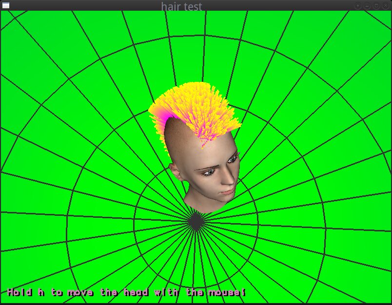
Hair rendering and simulation can be challenging, especially in real-time. There are many sophisticated algorithms for it (based on particle systems, hair mesh simulation, mass-spring systems and more) that can give very good results. But in this post, I will try to explain a simple and somehow hacky approach I followed in my first attempt to simulate hair (the mohawk hair of the video below) using a mass-spring system.
The code can be found here: https://github.com/hikiko/mohawk
(Before I start, a WARNING: This post was all an experiment… I started it at the same time I started the code and I was editing it at every massive commit. I found it a little frustrating to explain one idea or a hack I used in one commit and then a few commits later, realize that I don’t really need it anymore, remove it from the code and change the post too. So, after giving it some thought, I decided to not do so, and just explain why I rejected my initial ideas and how I realized that some hacks could be replaced by others that are better… But, this way, I ended up describing everything I’ve done and undone in the code in chronological order. Like a TL, verbose log of a version control system. Read it at your own risk!)
Step 1 (Prerequisite): Modelling the head.
First of all I needed a 3D head and a region on it that would be covered by the hair. I used two modelling tools for this job: Makehuman and Blender.
Makehuman is a tool to create human 3D models by modifying an existing 3D mesh. I’ve used it to create a human body, and then I used Blender to delete the polygons of the body that were not part of the head, and to name each object (since the head, the eyes, the eyebrows and the eyelids were separate 3D objects) and to correct its pivot point position. Then, I used vertex painting to mark the regions that I wanted to be covered by hair. I exported the head with the colored vertices in an FBX file and loaded it to my program using assimp. I chose the FBX format instead of an open one (like the obj that I usually use) because it can store information about the colored vertices and is compatible with assimp (OBJ doesn’t support colored vertices).
-
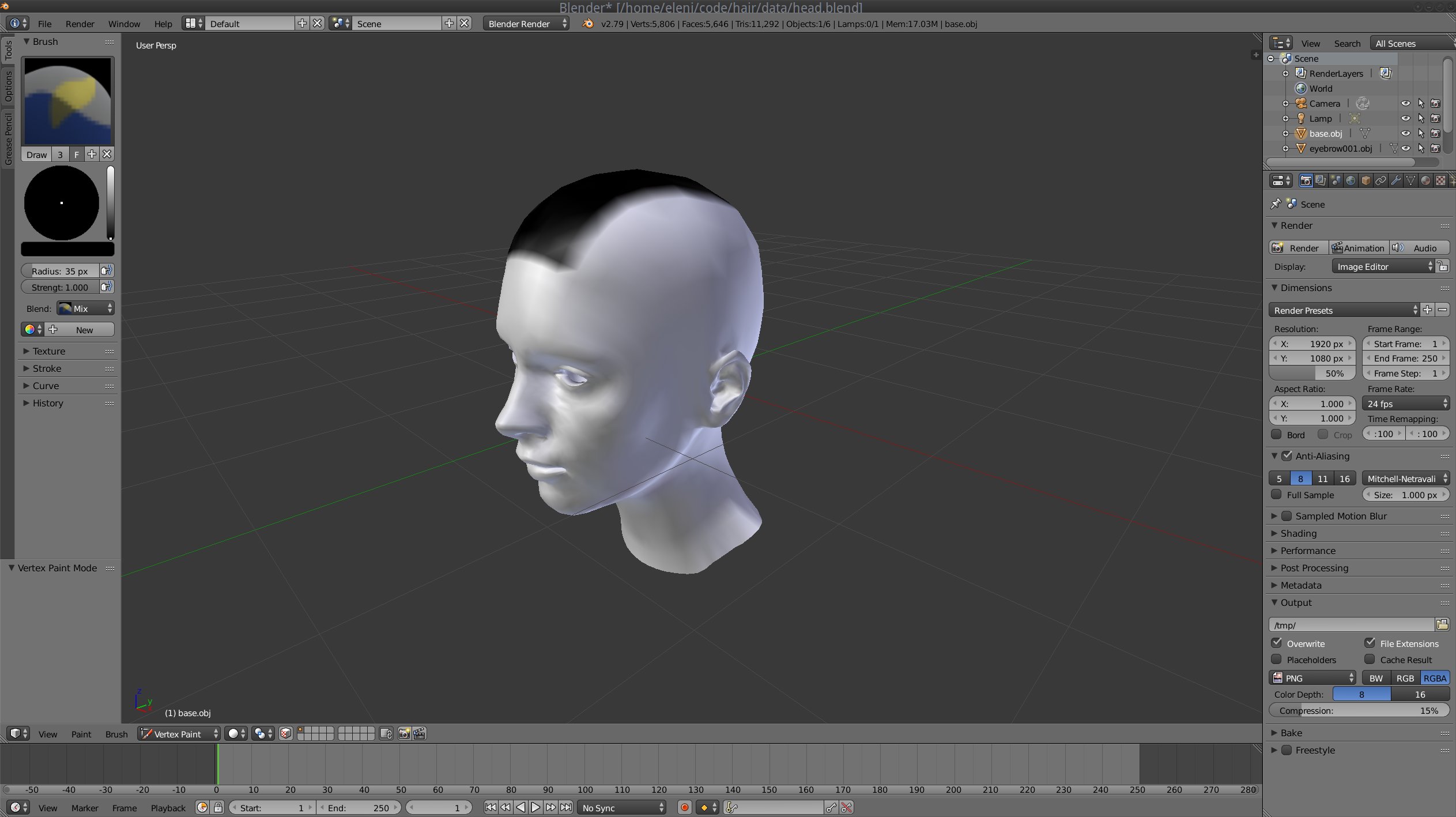
Vertex painting on Blender: here, I marked the head region that will be covered by hair.
-

Then, I loaded the head 3D model using assimp in my program.
You can check the mesh.h, mesh.cc and main.cc files for the details of the loading.
Step 2: Selecting the appropriate simulation system.
After having the head and the painted vertices, I had to decide what type of hair I wanted to create and what type of hair system I could use for that purpose (a points and springs system, particles, a mesh?).
Although initially I was thinking to use particles (easier), I finally decided to use a points-and-springs system, where each hair strand would be a spring animated by applying forces to it. The reason was that I wanted the hair to look mostly like a mohawk and less like a traditional haircut and with such a system I could sufficiently control the hair direction, as I will explain later. Particles are more suitable for long hair.
Step 3: Distributing the root points.
In order to distribute the roots on the “mohawk” part of the head I had colored previously, I decided to use a variation of the Poisson disk sampling method (an algorithm that places the samples “randomly” but checks that no two samples are too close to each other in order to generate an even but random-looking distribution). I also used a kd-tree to speed up these placements/comparisons.
Coding details:
I iterated through the painted vertices and found the triangles that belong to the region that I wanted to be covered by the mohawk (see get_spawn_triangle of hair.cc). At every iteration, I was repeatedly selecting random points using random barycentric coordinates on each randomly selected triangle of the mohawk, rejecting those that were close (I made the distance check using an arbitrary minimum distance as Poisson radius) to the already selected points. I also used a kd-tree to optimize these comparisons and reject the points faster (see Hair::init in hair.cc). I ended up with the mohawk covered by uniformly distributed points that would be my hair roots.
|
1 2 3 4 5 6 7 8 9 10 11 12 13 14 15 16 17 18 19 20 21 22 23 24 25 26 27 28 29 30 |
std::vector faces; kdtree *kd = kd_create(3); const float min_dist = 0.05; get_spawn_triangles(m, thresh, &faces); for(int i = 0; i < max_num_spawns; i++) { // Poisson int rnum = (float)((float)rand() / (float)RAND_MAX) * faces.size(); Triangle rtriangle = faces[rnum]; Vec3 bary; Vec3 rpoint = calc_rand_point(rtriangle, &bary); kdres *res = kd_nearest3f(kd, rpoint.x, rpoint.y, rpoint.z); if (res && !kd_res_end(res)) { Vec3 nearest; kd_res_item3f(res, &nearest.x, &nearest.y, &nearest.z); kd_res_free(res); if(distance_sq(rpoint, nearest) < min_dist * min_dist) continue; } HairStrand strand; /* weighted sum of the triangle's vertex normals */ strand.spawn_dir = normalize(rtriangle.n[0] * bary.x + rtriangle.n[1] * bary.y + rtriangle.n[2] * bary.z); strand.spawn_pt = rpoint; hair.push_back(strand); kd_insert3f(kd, rpoint.x, rpoint.y, rpoint.z, 0); } kd_free(kd); for(size_t i=0; i<hair.size(); i++) { hair[i].pos = hair[i].spawn_pt + hair[i].spawn_dir * hair_length; } |
And this is how the roots of ~400 hair strands were looking at that point:
-
Hair roots distributed in the mohawk using the Poisson disk sampling.
-
Another view of the hair roots distribution.
Step 4: Creating the strands and their anchor points.
At this step, I knew the position of each hair root, so I could easily render the hair strands using the normal direction at each point. But I needed more information to be able to animate the hair:
|
1 2 3 4 5 6 7 8 |
struct HairStrand { Vec3 pos; Vec3 velocity; /* directions relative to the spawn point */ Vec3 anchor_dirs[3]; Vec3 spawn_pt; Vec3 spawn_dir; }; |
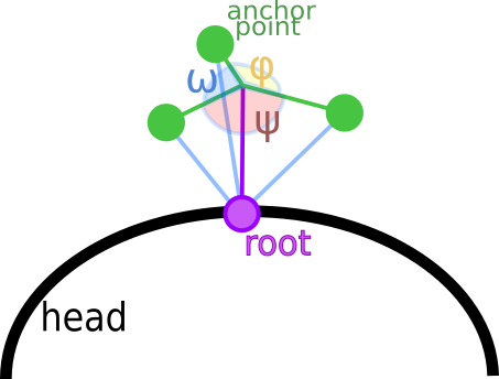
In the struct above, the spawn_point is the root position and the spawn_dir is the direction of the hair strand. In order to modify these later, I used three anchor directions to apply forces to each hair (more details in the animation step). In the image below, the anchor points of each purple hair can be seen in green color around it. Their directions are relative to the spawn point. To calculate the anchor points directions, I had to calculate an orthonormal basis using the spawn direction, a new normal and their cross product as i, j, k vectors (again see Hair::init in hair.cc).
The green anchor points could apply forces from 3 directions to the hair strand (green line segments). Their directions relatively to the root (spawn point) are denoted in blue, and could be calculated by multiplying the basis matrix with the vectors:
- v1 = (cos(ω), sin(ω), 0)
- v2 = (cos(ψ), sin(ψ), 0)
- v3 = (cos(φ), sin(φ), 0)
where ω = φ = ψ.
The position in the struct is the hair strand position (spawn_pt + spawn_dir * hair length) and the velocity vector is 0 at this point (static hair).
In the image below you can see the anchor points and the hair strands of this step visualized (I reduced the hairs from 400 to 4 for the screenshot).
-
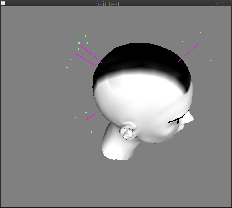
Some hair strands with their anchor points.
Step 5: Forces!
So far, I had a head and some static hair surrounded by anchor points. In order to animate them, I needed to decide how to apply the forces to them. One simple thing I could do, that wouldn’t involve many difficult calculations and factors to control, was to make the hair follow the motion of the head.
So, before anything else, I needed to add some motion to the head. I used the mouse motion when a key is pressed (‘H’ or ‘h’) to calculate the rotation around the x and z axes. I then created a rotation matrix to multiply with the modelview before the rendering of the head and to use it for the hair motion simulation. The code was quite simple (check the keydown, keyup functions as well as the motion and display ones in the main.cc).
At this point, I realized that my 3 anchor points could be reduced to only one, simplifying a lot the calculations. What I really wanted to achieve was to make each hair strand follow the motion of the head and then apply a force towards the resting position. So instead of having 3 anchor points surrounding the hair, I could apply a force from each moved hair end towards the hair end.
In a simple case (no optimisations), the hair movement would be something like that:
The force direction is demonstrated with the yellow line segment, and the new anchor point that replaces the previous 3 is the point in green. Note that the velocity must decrease in time otherwise the animation after moving the head will never stop.
The mohawk simulation of the ~400 hair strands was looking quite realistic with this change, so I kept it:
Coding details:
First of all, I changed my HairStrand struct to the much simpler:
|
1 2 3 4 5 6 |
struct HairStrand { Vec3 pos; Vec3 velocity; Vec3 spawn_pt; Vec3 spawn_dir; }; |
In this struct, pos is the hair end position, velocity is the hair strand velocity vector, spawn_pt is the root in local coordinates and spawn_dir is the direction of the hair in the resting position (when no forces are applied).
To render a hair strand line at each moment, I needed to calculate its end and root positions and update its pos value.
Update function:
|
1 2 3 4 5 6 7 8 9 10 11 |
void Hair::update(float dt) { for(size_t i = 0; i<hair.size(); i++) { Vec3 hair_end = hair[i].spawn_pt + hair[i].spawn_dir * hair_length; Vec3 anchor = xform * hair_end; Vec3 force = (anchor - hair[i].pos) * K_ANC; Vec3 accel = force; /* mass 1 */ hair[i].velocity += ((-hair[i].velocity * DAMPING) + accel) * dt; hair[i].pos += hair[i].velocity * dt; } } |
Here, I calculated the hair_end in local space and multiplied it with the head transform to find the anchor point position in the view space.
As I had the previous position, I could calculate the force direction as anchor point - pos multiplied by the K_ANC that is the spring constant and was chosen by trial and error. I made the assumption that the hair mass is 1 to keep things simple, and as a result the acceleration vector was equal to the force. I then calculated the motion velocity from the physics formula: v = a * dt; (where v is the velocity, a the acceleration, dt the time), but with some modifications to satisfy the following restrictions:
- As each hair motion should change continuously to appear more natural, I needed to add the new velocity to the previous velocity.
- But I also had to reduce the acceleration by a damping factor (again selected by trial and error) otherwise the spring would never rest (hairs are not perfect strings).
So my velocity formula became:
|
1 |
new velocity vector = acceleration * dt - previous velocity vector * damping factor * dt; |
Rendering of the hair strands was quite simple (mainly because I’ve used all my favorite “legacy” OpenGL functions to draw lines with glBegin, glEnd):
|
1 2 3 4 5 6 7 8 9 10 11 12 13 14 15 16 17 |
void Hair::draw() const { glPushAttrib(GL_ENABLE_BIT); glDisable(GL_LIGHTING); glLineWidth(3); glBegin(GL_LINES); for(size_t i=0; i<hair.size(); i++) { glColor3f(1, 0, 1); Vec3 p = xform * hair[i].spawn_pt; glVertex3f(p.x, p.y, p.z); Vec3 dir = normalize(hair[i].pos - p) * hair_length; Vec3 end = p + dir; glVertex3f(end.x, end.y, end.z); } glEnd(); glPopAttrib(); } |
In the snippet above, each hair strand is a line segment (GL_LINE) from the transformed spawn point (hair strand root in the view space) to an end calculated as root + hair direction where the hair direction is calculated as: (end position - root) * hair length. The reason that I normalized the direction, was that I wanted the hair strands to have the same length all the time (and springs don’t).
Step 6: Optimizations!
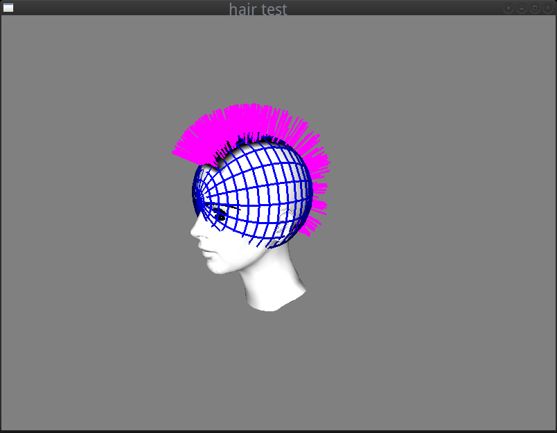
In the GIF image above, I intentionally used relatively small motions and forces. The reason was that moving the head more aggressively would cause the hair strands to move so much that some of them would end up being rendered inside the head mesh… Like in the following image:
And that wasn’t exactly what I wanted for my simulation…
What I needed to do to fix the artifact, was some sort of collision detection with the head in order to correct the motion of the hair strands that would “enter” it before they enter it. As it would be difficult to calculate the collision with the actual head 3D model, I decided to do some hacky approximation.
My first thought (spoiler alert: a bad idea!) was to calculate the collision with a sphere that had similar dimensions with the head.
For that, I needed to find some convenient center and diameter to construct it. Although I’ve selected these values by trial and error, I’ve done some quick checks first to get an idea of what would a “good” size be:
I exported the head 3d model in OBJ format from Blender (see step 1) and I found the vectors of the head that were in this form:
|
1 2 3 4 5 6 7 |
v -0.332900 0.492626 1.371101 v -0.335900 0.483727 1.371401 v -0.295300 0.484226 1.376201 v ... . . . |
I then calculated quickly the maximum distances in x, y, z axes with a script and used them as a reference for the size of the sphere diameter (they were in the same coordinate system).
Here’s an example of a “convenient” sphere:
The collision detection at this point was quite simple to calculate. I’ve written a CollSphere class in the file object.h (intending to make it inherit from a generic collider class later, so that I can also perform collision detection with other objects for other effects).
And here is the “trick” explained:
|
1 2 |
Vec3 new_pos = hair[i].pos + hair[i].velocity * dt; hair[i].pos = handle_collision(new_pos); |
After calculating the hair position in the update function the handle_collision function was called. This function only updates the hair position if the hair end is not falling inside the head.
|
1 2 3 4 5 6 7 8 9 10 11 12 13 |
Vec3 Hair::handle_collision(const Vec3 &v) const { /* if we transform the center and the radius of the collider sphere * we might end up with a spheroid, so better just multiply the * position with the inverse transform before check for collisions :*/ Vec3 new_v = inverse(xform) * v; for(size_t i=0; i<colliders.size(); i++) { if(colliders[i]->contains(new_v)) { new_v = colliders[i]->project_surf(new_v); } } return xform * new_v; } |
Note that the comparison had to take place with all the vectors being in the same coordinate system.
Then I checked if the point is inside the sphere:
|
1 2 3 4 |
bool CollSphere::contains(const Vec3 &v) const { return length_sq(v - center) >= radius * radius; } |
As it happened before with the anchor points, I soon realized that this trick would never work well with the mohawk: the hair strands were too long and I was only using the hair end to check for collisions. And in most cases the end was not colliding with the head but other parts of the hair strand did . Checking with another point of the hair strand that is closer to the root would only minimize the problem, as the only accurate check, would be a check with the root that would test nothing… 😀 Using more points across the hair could probably work better but it would be complex and not worth the effort. So, I’ve decided to keep the collision detection mechanism for other future effects (eg. to check for collisions with flying objects) but not use it in this particular case.
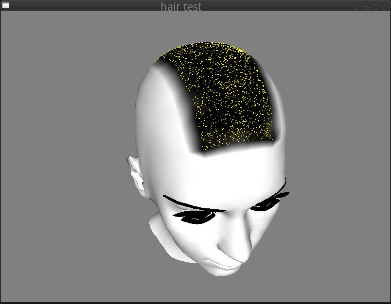
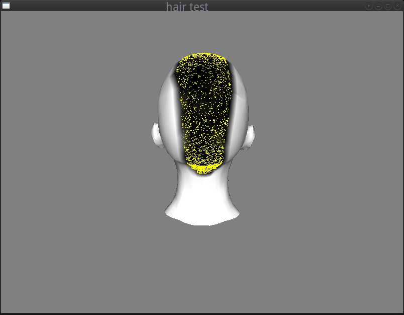
The following screenshot is an attempt to show better how problematic this idea was. I’ve rendered some points in random positions and I painted in yellow those that if they were hair ends would fall inside the head and in blue those that would fall outside, and then I rendered the head in wireframe. It became more obvious why it would be almost impossible to fix the artifact with this hack: the check is accurate only for the points that lie very very closely to the head surface:
So at this point, I had to abandon the idea to use the sphere for collisions and think of something better. And I soon realized that I could only use the hair direction to test whether each hair is about to enter the head in the next drawing. And to avoid the collision of the hair strand with the head, I could just project the hair strand on the head surface…
How?
With a few simple tests:
In the update function I already had the code that calculates the new hair position in world space:
|
1 |
Vec3 new_pos = hair[i].pos + hair[i].velocity * dt; |
I also had the spawn direction in local coordinates (hair[i]->spawn_dir). This direction in world space would match the normal, as it is the direction of the hair in the rest position. To bring it in world space I only needed to apply the current head transform without the translations:
|
1 |
Vec3 normal = xform.upper3x3() * hair[i].spawn_dir; |
I also needed the hair root position and the hair direction to be in the same space (when I transformed the position I needed to keep the translation so I used the whole 4×4 matrix):
|
1 2 |
Vec3 root = xform * hair[i].spawn_pt; Vec3 dir = new_pos - root; |
Then I performed the check for collisions as follows:
|
1 2 3 4 5 6 |
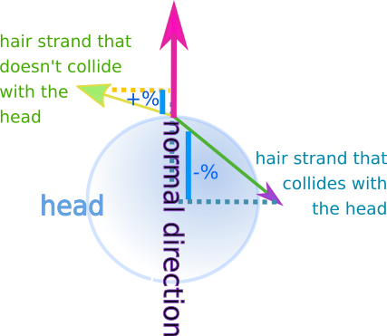
normal.normalize(); float d = dot(dir, normal); if(d < 0) { new_pos += -d * normal; } hair[i].pos = new_pos; |
The dot product could show if there was a collision because:
- The dot product between the hair end new position and the normal, when the normal is normalized (length 1), is indicative of the proportion of the normal that would be covered if we could project the hair strand on it (see the blue line segments in the image below).
- When the hair collides with the head, the dot product is negative. When it lies above the surface, it is positive.
After this step the hair motion was wayyyy much better:
Step 7: Textures, Materials, Head Surroundings…
After the hair simulation was fixed, the remaining things to do were to load some textures and materials (and fix some million bugs) to make the hair look nice and create some sort of environment around the head to have a better understanding of the camera rotations. The first was mainly work with assimp (see files: mesh.h/cc and the display function in main.cc) but the latter was again quite tricky…
I’ll try to explain how I achieved this “environment map”-like gradient around the head:
First of all, at the time I reached this point, I realized, that most of the hair simulation was done and I hadn’t loaded a single shader or a texture (apart from those that I added later for the head, the eyebrows etc from assimp). So, I thought that it would be quite interesting and challenging to continue like that and to try to create a surrounding environment without using cube maps or any procedural effect that would require shaders.
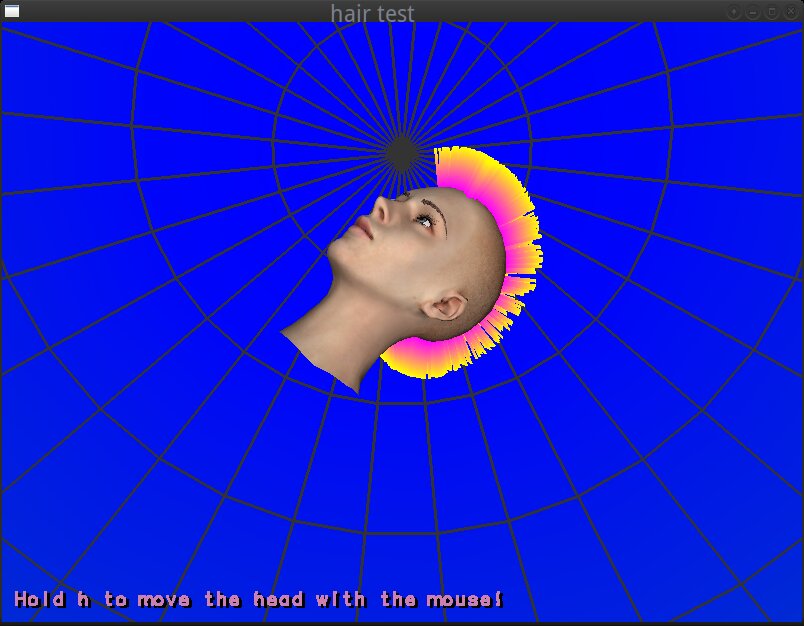
Instead, I used a glutSolidSphere as a “sphere map” which I rendered around the scene. Then, I generated an one-dimensional texture with the gradient (by calling following function with green and blue as colors):
|
1 2 3 4 5 6 7 8 9 10 11 12 13 14 15 16 17 18 19 20 |
static unsigned int gen_grad_tex(int sz, const Vec3 &c0, const Vec3 &c1) { unsigned char *pixels = new unsigned char[sz * 3]; for(int i=0; i<sz; i++) { float t = (float)i / (float)(sz - 1); Vec3 color = c0 + (c1 - c0) * t; pixels[i * 3] = color.x * 255; pixels[i * 3 + 1] = color.y * 255; pixels[i * 3 + 2] = color.z * 255; } unsigned int tex; glGenTextures(1, &tex); glBindTexture(GL_TEXTURE_1D, tex); glTexParameteri(GL_TEXTURE_1D, GL_TEXTURE_MIN_FILTER, GL_LINEAR); glTexParameteri(GL_TEXTURE_1D, GL_TEXTURE_MAG_FILTER, GL_LINEAR); glTexParameteri(GL_TEXTURE_1D, GL_TEXTURE_WRAP_S, GL_CLAMP_TO_EDGE); glTexImage1D(GL_TEXTURE_1D, 0, GL_RGB, sz, 0, GL_RGB, GL_UNSIGNED_BYTE, pixels); delete [] pixels; return tex; } |
and I applied the 1D texture on the sphere.
And that was basically the tricky part:
To begin with, the glutSolidSphere function does not generate texture coordinates. So, I had to create some myself. After that, I needed a way to map the 1D gradient to the 3D sphere.
The whole idea is implemented in these lines:
|
1 2 3 4 5 6 7 8 9 10 11 12 13 14 15 16 17 18 19 20 21 |
float plane[4] = { 0, 0, 0.5 / 350, 0.5 }; glPushMatrix(); glRotatef(90, 1, 0, 0); glPushAttrib(GL_ENABLE_BIT); glDisable(GL_LIGHTING); glEnable(GL_TEXTURE_1D); glBindTexture(GL_TEXTURE_1D, grad_tex); glFrontFace(GL_CW); glEnable(GL_TEXTURE_GEN_S); glTexGenfv(GL_S, GL_OBJECT_PLANE, plane); glTexGeni(GL_S, GL_TEXTURE_GEN_MODE, GL_OBJECT_LINEAR); glColor3f(1, 1, 1); glDepthMask(0); glutSolidSphere(350, 16, 8); glDisable(GL_TEXTURE_1D); |
The function glTexGen generates the texture coordinates for the current vertices (in our case the sphere’s vertices) by using the distance of each vertex from a plane (GL_OBJECT_PLANE) in local space as texture coordinate. As the name of the variable plane indicates, it is the array of the 4 values that define the plane equation that will be used for this purpose:
Eq: ax + by + cz + d = 0
where the values a, b and c define the normal (a, b, c) of the plane and d is the translation (or distance from the origin).
And here’s how I selected the values of the plane equation in order to use a good plane for the mapping:
As the sphere’s orientation when I rendered it was such that the poles of the sphere were falling on the z axis, I knew that the normal of the plane should be of the form (0, 0, value) (aligned to the z-axis), because I needed to apply the 1D gradient from the north pole to the south pole of the sphere. If the plane equation was (0, 0, 1, 0) and the sphere had a radius of 1 unit, then, the gradient would be repeated twice (once from the north pole to the equator, and once from the equator to the south pole). For that I needed to translate the plane by half sphere.
And so my plane equation became: (0, 0, 0.5/350, 0.5) (because the sphere had radius 350 as you can see in the glutSolidSphere call) and I wanted to shift the texture coordinates by 0.5 so that the final range become [0, 1].
With this trick, I mapped the 1D gradient texture to the solid sphere. Then I rendered a wire sphere (glutWireSphere) to make the camera rotations more obvious.
The 2 poles of the spheres:
And I think, that was all…
Epilogue: Blah blah blah and some acknowledgments.
So far, I only had theoretical knowledge about some hair rendering algorithms, but I hadn’t written any program myself. I started this little hack in August, as an experiment inspired by the hair simulations I’ve seen in the Computer Animation Festival on SIGGRAPH2018 where I went with Igalia.
Since then, I abandoned it around 1 million times, as I always had something else to do, and I suddenly remembered it a few weeks ago, while I had to stay away from my computer and spend my time productively by looking at the ceiling in a philosophical mood about life, the universe and the use of spring-like hair strands to create mohawks for hairless 3D heads… :p Anyway, I decided to finish it during the Christmas holidays (because never is too late) and see if I can finally achieve a mohawk-like result.
I have some ideas on how to further improve it and for effects I could add, which I might implement and explain in a follow-up post (or I might not, as I usually abandon the almost-done-hobby-projects to start new ones to leave unfinished… :p).
Anyway, in closing,
- I ‘d like to thank Nuclear for his libraries (I borrowed his math library, his library to load images and his kd-tree code from his github) and for his help with the modelling tools and some (millions) questions I had,
- as well as Igalia that sends us to the most cool conferences to get ideas :).
And some good news:you have finally reached THE END of this post!
Happy new year!