There are several methods to create and display a terrain, in real-time. In this post, I will explain the approach I followed on the demo I’m writing for my work at Igalia. Some work is still in progress.
The terrain had to meet the following requirements:
- its size should be arbitrary
- parts outside the viewer’s field of view should be culled
Parameters that describe the terrain
For reasons that will become obvious when I explain the terrain generation and drawing, I decided to use a heightfield made by tiles and I used the following parameters to generate it:
|
1 2 3 4 5 6 7 8 9 10 11 12 13 14 |
/* parameters needed in terrain generation */ struct TerrainParams { float xsz; /* terrain size in x axis */ float ysz; /* terrain size in y axis */ float max_height; /* max height of the heightfield */ int xtiles; /* number of tiles in x axis */ int ytiles; /* number of tiles in y axis */ int tile_usub; int tile_vsub; int num_octaves; /* Perlin noise sums */ float noise_freq; /* Perlin noise scaling factor */ Image coarse_heightmap; /* mask for low detail heightmap */ }; |
Let’s explain them a little bit:
Imagine the terrain as a xsz * ysz grid of tiles where each tile is a subdivided in usub, vsub smaller parts. Each grid point can have an “arbitrary” height (we ‘ll see later how we calculate it) that cannot exceed the maximum height: max_height. The number of tiles in each terrain axis is xtiles for the x-axis and ytiles for the y-axis (that is practically the z-axis of out 3-D space). The variables tile_usub and tile_vsub show the number of subdivisions of each tile.
Note that in general, I use the u, v notation in normalized spaces and the x, y for the world space.
The variables num_octaves and noise_freq and the coarse_heightmap image are used to calculate the heights in different terrain points and will be explained later.
Generating the geometry, applying the textures
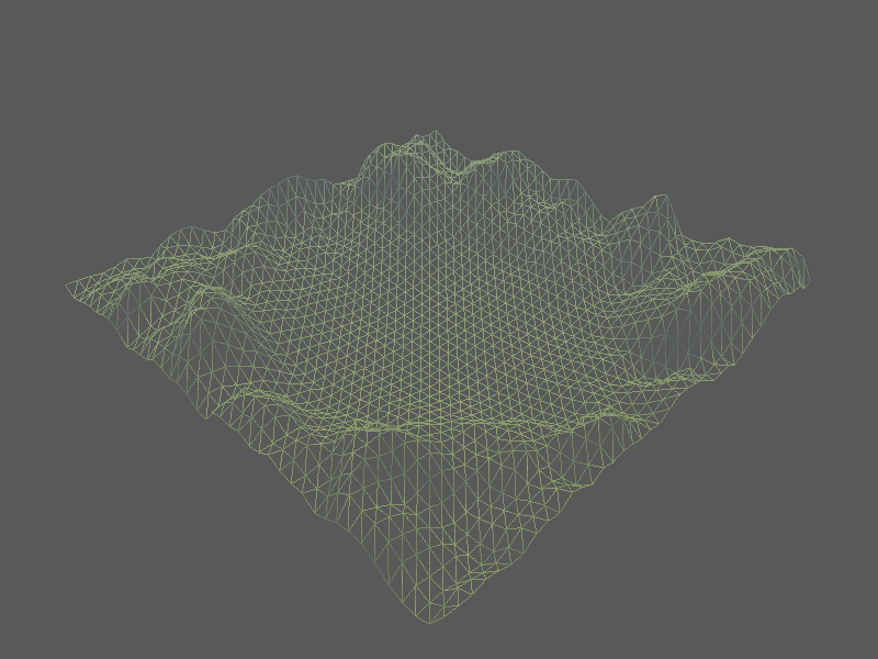
We ‘ve already seen that the terrain is a grid of xsz * ysz with xtiles * ytiles tiles, that are subdivided by tile_usub in the x-axis and by tile_vsub in the z-axis. In order to generate a height at every point of this grid, I needed to calculate uniformly distributed random values, like those of Perlin Noise (PN). But I also needed some higher distortions for “mountains” and “hills” here and there that cannot be simulated with PN. For them I used a function that calculates the sum of some Perlin Noise frequencies and results to a fractal-like heightfield. The number of the PN sum octaves and the frequency (num_octaves, noise_freq) can be customized depending on how much distortion we want.
Having a terrain with spreaded random-looking mountains is nice, but it would be much better if we could further customize its appearence to become more suitable for our scene. For example, I wanted to place a number of objects in the middle of the terrain, so I wanted it to look more flat in the center. Also, I wanted to put some high mountains at the edges to hide some skybox parts (for example mountains and buildings that were part of the skybox texture and looked ugly). In order to modify the terrain shape, I used a grayscale image, the coarse_heightmap, as a mask and I multiplied the terrain height values with the mask intensities (I’ll explain this better later). The mask was like the image below:

Since the heightmap is black at the center (=> the itensity values there are close to 0) the height in the middle will be low and the terrain will look flat, whereas at the edges, where the intensity takes its maximum values, the height values will have a value close to their original height. If you get a more careful look at Image 1 and Image 2 you will understand better the relationship between the terrain heights and the mask intensities.
That’s the function that generates each tile’s heightfield by calculating the height by taking the sum of the Perlin noise frequencies for each tile:
|
1 2 3 4 5 6 7 8 9 10 11 12 13 14 15 |
float Terrain::get_height(float u, float v) const { float sn = gph::fbm(u * params.noise_freq, v * params.noise_freq, params.num_octaves); sn = sn * 0.5 + 0.5; if(params.coarse_heightmap.pixels) { Vec4 texel = params.coarse_heightmap.lookup_linear(u, v, 1.0 / params.tile_usub, 1.0 / params.tile_vsub); sn *= texel.x; } return sn; } |
Note that the function performs the calculations in u-v space. I found it convenient to write a similar function for the world space to use it in other places.
Now, let’s see how we use the coarse_heightmap on top of that:
The coarse_heightmap image (Image 2) has a very low resolution of 128x128 which means that if we just lookup the closest pixel value for each terrain point, and the terrain is big, many terrain points will map to the same pixel and we’ll start seeing aliasing. To avoid this artifact, I used bilinear interpolation among the pixel’s neighboring pixels by taking into account the distance of the terrain point from each pixel of the neighborhood.

The following video is a preview of this early stage of the demo where you can see the terrain from different views (as well as a cow called Spot :P):
Improvements:
fog:
A good trick to make the terrain edges appear more distant that they really are and have a more realistic horizon, is to add some fog that is more dense in the more distant terrain points and less dense at the points that are close to the viewer. The fog can be simulated by interpolating the terrain color at each pixel with a color that looks like the sky (I used a light blue here). The interpolation factor must be a function of the distance between the point and the viewer. I used the following function:
e(-density * distance)
(taken by the glFog OpenGL manpage). I hard-coded the density to a value that looked good and I used the -pos.z as the distance where pos is the vertex position in the View space.
Image 4 shows the result of this operation:
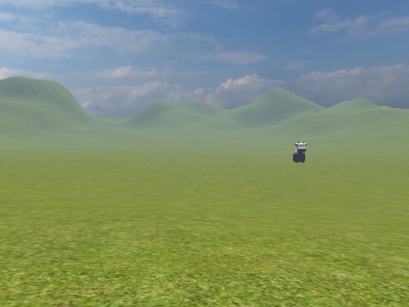
iMage based LIGHTING:
The idea behind the IBL is that instead of using point lights with a standard position in our 3D world, we can calculate the lighting as the radiance coming from each skybox pixel. For this purpose, we need an irradiance map. I avoided the overhead of calculating one by using this nice tool I’ve found on github: cmft to pre-calculate it from the images of my skybox. Then, I used the normal direction at each terrain point (in world space coordinates) to sample the map and I calculated the color inside the pixel shader:
|
1 2 |
vec4 itexel = textureCube(dstex, normalize(world_normal)); vec3 object_color = diffuse.xyz * texel.xyz * itexel.xyz; |
As you can guess the world_normal is the normal in world space (modelling transformation) and the object_color the color we get if we multiply our diffuse color from the material with the texel value (from the terrain texture) and the irradiance map texel value (itexel). The result of this operation can be seen in this video:
TODO LIST
Although the terrain looks better with these additions, I think that it can be further improved if I add the following things:
- Multiple textures for different parts of the terrain
- (Maybe) specular color calculated by the irradiance map (since atm I have support for diffuse only)
Performance optimisations:
I also want to optimize its performance by adding:
- View Frustrum Culling: The idea is that we only draw the terrain tiles that are visible (part of the view frustrum).
- Tessellation shaders: use TC, TE shaders to improve the terrain tesselation.
Some of the above TODOs are in progress, some are still in my wishlist but all of them all TL;DR to be analyzed in this post anyway.
I will post about these additions as soon as I finish them, stay tunned! 😉
![]()