This post is about different depth aware techniques I tried in order to improve the upsampling of the low resolution Screen Space Ambient Occlusion (SSAO) texture of a VKDF demo. VKDF is a library and collection of Vulkan demos, written by Iago Toral. In one of his demos (the sponza), Iago implemented SSAO among many other graphics algorithms [1]. As this technique is expensive, he decided to optimize it by using lower resolution textures and render target, which he then upsampled to create a full resolution image that he blended with his original one to display the result. For the upsampling he used linear interpolation, and as expected he observed many artifacts that were increasing by lowering the SSAO textures resolution.
Some time ago, I started experimenting with methods to improve that upsampling in order to familiarize myself with Vulkan. The most promising ones seemed to be the depth-aware techniques:
Depth-aware algorithms and improvements
A depth-aware technique is a technique where we use depth information from the image in order to get some insight about the shape and the discontinuities of the surfaces before attempting the reconstruction. For that, we usually use a downsampled z-buffer (that has the same resolution with the low resolution image) from which we gather information that helps us select the best sample from the downscaled texture during the upsampling.
So, every depth-aware technique has 2 parts to be improved:
- The downsampling of the original Z-buffer: we have to make sure it contains the most valuable information about the scene
- The upsampling of the texture using information from this Z-buffer and probably other resources and some sort of interpolation
Nearest depth sampling
The most common depth-aware algorithm to upsample the texture is the nearest depth algorithm which is explained very well in this paper from NVIDIA [2].
The idea is that in every 2×2 neighborhood of the downsampled z-buffer, we find the sample whose depth is closer to the original depth (from the high resolution depth buffer, we need both z-buffers in the pass) and we use its uv coordinates to select a sample from the texture we would like to upsample.
So, my first experiment was to compare the linear upsampling with the nearest depth upsampling. For the depth-buffer downsampling, I used the maximum depth in each 2×2 neighborhood.
Comparison #1: Linear Sampling vs Nearest Depth Sampling
First of all some information about the SSAO.
- Number of samples: 24
- Target resolution: 1/2 of the original
- Resolution in which I took the following screenshots: 1/8 of the original
- Parameters:
123456789const float WIN_WIDTH = 1920.0f;const float WIN_HEIGHT = 1080.0f;const uint32_t SSAO_NUM_SAMPLES = 24;const float SSAO_RADIUS = 0.75f;const float SSAO_BIAS = 0.05f;const float SSAO_INTENSITY = 3.0f;const uint32_t SSAO_BLUR_SIZE = 2; // Min=0 (no blur)const float SSAO_BLUR_THRESHOLD = 0.05f; // Min > 0.0
Let’s see some screenshots:
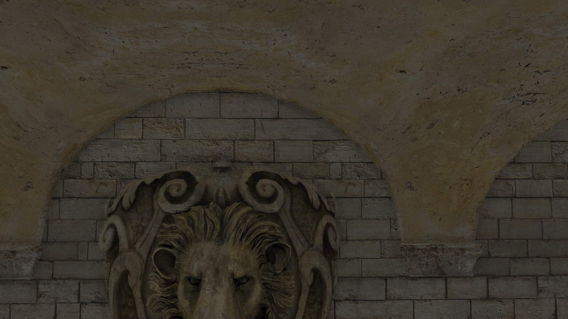
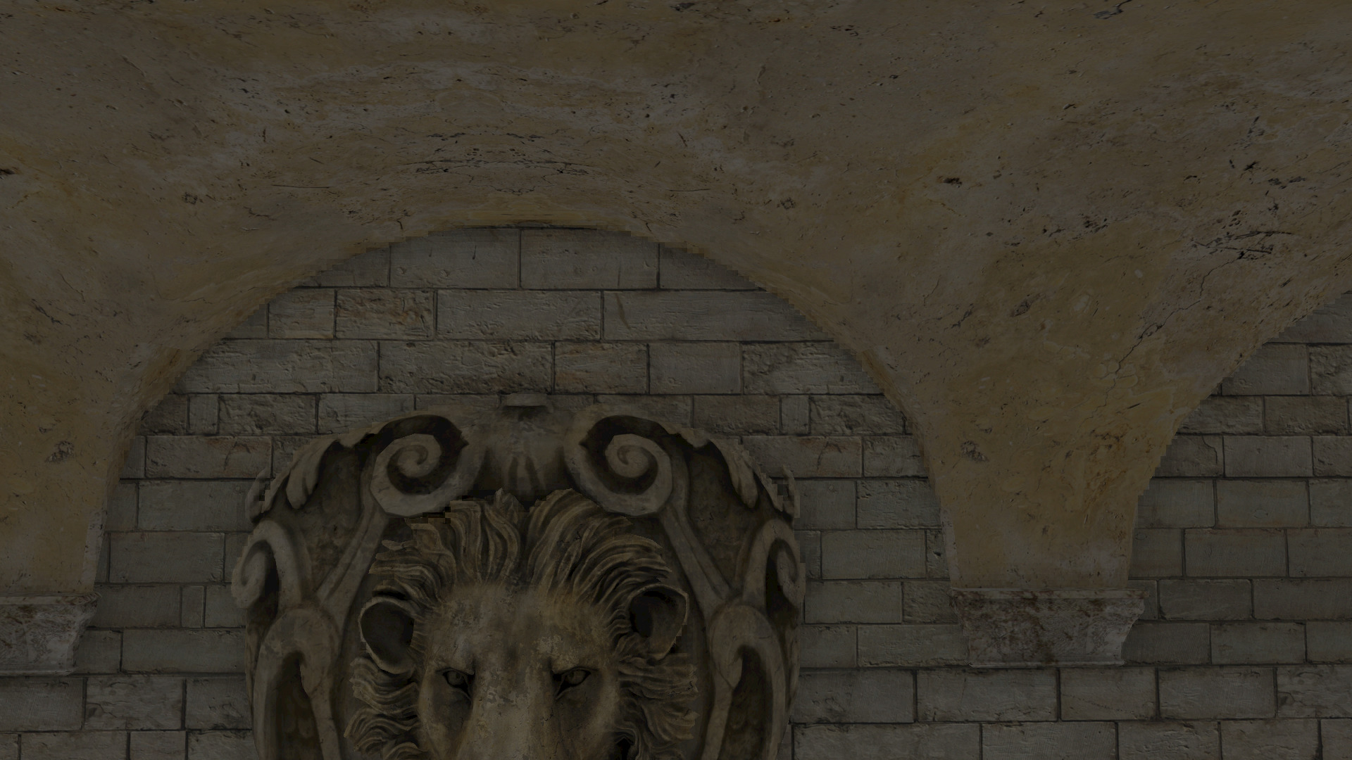
If you carefully examine these screenshots (taken at the 1/8 of the original resolution) the curve of the first is slightly less pixelized but not significantly better.
But the overall scene (below) looks equally bad when I lower so much the resolution that I can’t really tell the difference between the two methods:
And the following in 1/4 resolution:
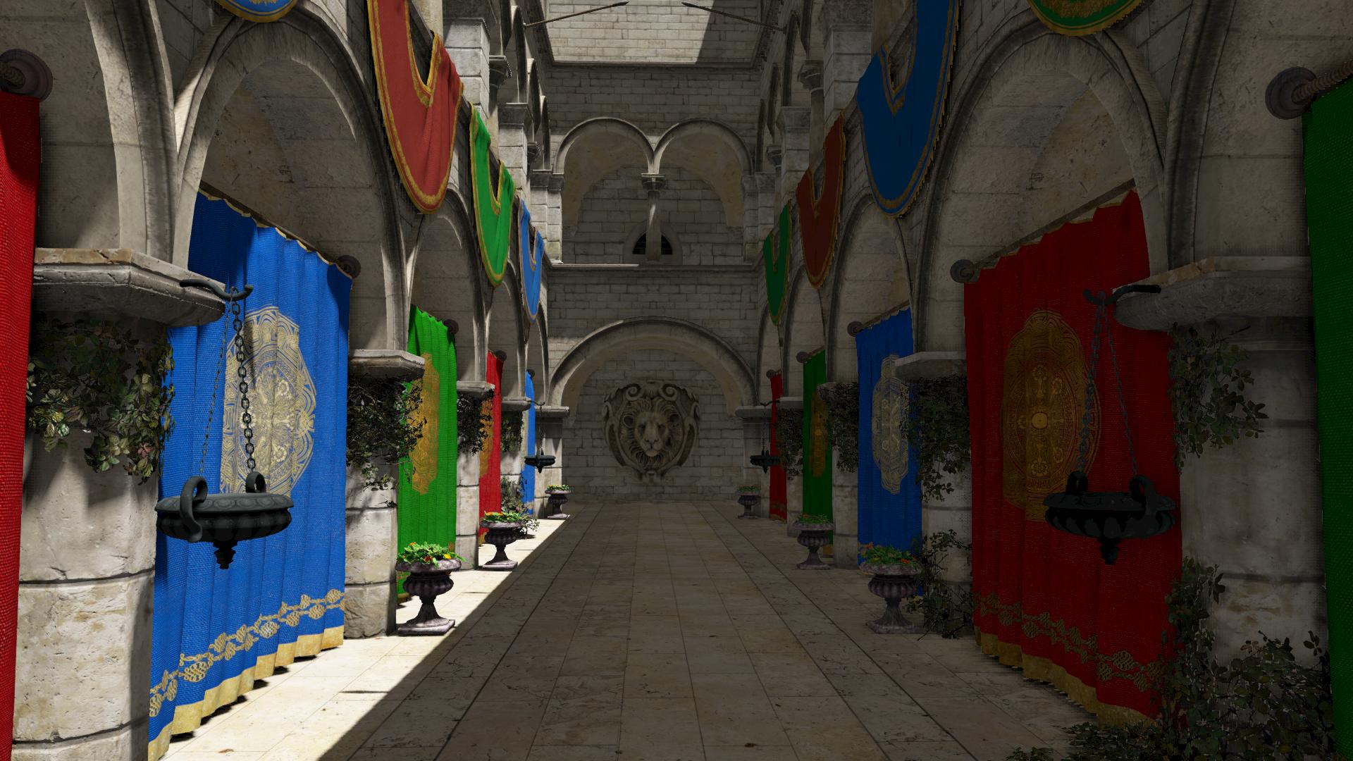

Here the images are almost identical. Nearest depth alone is hardly an improvement.
Note that the screenshots are taken in such low resolution to make the artifacts too visible. In half resolution for example (that is a reasonable resolution for the SSAO) the artifacts are significantly less for both sampling techniques, and the comparison is more difficult.
Target resolution (1/2 of the original)
The following video shows a comparison of Linear Interpolation (lerp) and Max/Nearest depth combination from different views. As we move the camera and examine different views of the scene, we can see more clearly that the nearest depth has an advantage in the edges and the corners and where we have depth discontinuities (which means than not all the samples of the neighborhood lie on the same surface) but I think that there are still many artifacts to make it acceptable:
The result is a little bit disappointing.
Vulkan and shaders details
Despite the disappointing results, I will share some implementation details as they might help also understand the follow up experiments (that I will probably analyze in some follow up posts):
Downsampling:
Vulkan side I needed a special pass that takes as input (depth attachment) the original depth buffer and renders to a depth render target of the size of the SSAO pass render target. I hardcoded the geometry of the quad to which I mapped the texture inside the vertex shader to keep things simple (bad idea as I had a bug there but that’s another story, without the bug it would have been a good idea… :p).
Some options I used for this pass and might be interesting were the following:
– render target image options:
|
1 2 3 4 5 6 7 8 9 |
VK_IMAGE_TYPE_2D, VK_FORMAT_D32_SFLOAT, VK_FORMAT_FEATURE_DEPTH_STENCIL_ATTACHMENT_BIT | VK_FORMAT_FEATURE_SAMPLED_IMAGE_BIT, VK_IMAGE_USAGE_DEPTH_STENCIL_ATTACHMENT_BIT | VK_IMAGE_USAGE_SAMPLED_BIT, VK_MEMORY_PROPERTY_DEVICE_LOCAL_BIT, VK_IMAGE_ASPECT_DEPTH_BIT, VK_IMAGE_VIEW_TYPE_2D |
– render pass options for the depth attachment:
|
1 2 3 4 |
VK_ATTACHMENT_LOAD_OP_DONT_CARE, VK_ATTACHMENT_STORE_OP_STORE, VK_IMAGE_LAYOUT_UNDEFINED, VK_IMAGE_LAYOUT_DEPTH_STENCIL_ATTACHMENT_OPTIMAL |
– pipeline
|
1 2 3 4 5 |
true, /* enables both depth test and write */ VK_COMPARE_OP_ALWAYS, /* should always pass */ VK_PRIMITIVE_TOPOLOGY_TRIANGLE_STRIP, VK_CULL_MODE_BACK_BIT, /* better set to none while debugging */ |
In order to override the gl_FragDepth both the depth writes and the depth test were enabled and the VK_COMPARE_OP_ALWAYS was set. Having an OpenGL background I found this totally weird as my first thought would be to disable the depth test and enable the writes (at least in OpenGL I wouldn’t attempt to write to the z-buffer with the depth test enabled). But as the Vulkan VK_COMPARE_OP_ALWAYS makes the test always pass the result is the same.
and finally for the sampler I used the layout:
|
1 |
VK_IMAGE_LAYOUT_DEPTH_STENCIL_READ_ONLY_OPTIMAL |
Now that I mentioned the sampler…
One thing I like in Vulkan is that the texture and the sampler are separate objects. You can reuse the sampler with many textures. Modern OpenGL versions allow this with a more complex (in my opinion) way and some years ago the texture data and the sampling state were part of the same texture object. Vulkan seems to be designed to allow reusing the resources.
Anyway, let’s get a look at the shaders…
For the downsampling, the shaders were really short. The vertex shader creates a quad:
|
1 2 3 4 5 6 7 8 9 10 11 12 13 14 15 16 |
#version 430 #extension GL_ARB_separate_shader_objects : enable layout(location = 0) out vec2 out_uv; const vec2 vdata[] = vec2[] ( vec2(1.0, 1.0), vec2(1.0, 0.0), vec2(0.0, 1.0), vec2(0.0, 0.0)); void main() { out_uv = vdata[gl_VertexIndex]; gl_Position = vec4(vdata[gl_VertexIndex] * 2.0 - 1.0, 0.0, 1.0); } |
and the fragment shader only selects the maximum in each 2×2 neighborhood:
|
1 2 3 4 5 6 7 8 9 10 11 12 13 14 15 |
#version 460 #extension GL_ARB_separate_shader_objects : enable layout(location = 0) in vec2 in_uv; layout(set = 0, binding = 0) uniform sampler2D tex_depth; void main() { float d1 = textureOffset(tex_depth, in_uv, ivec2(0, 0)).x; float d2 = textureOffset(tex_depth, in_uv, ivec2(0, 1)).x; float d3 = textureOffset(tex_depth, in_uv, ivec2(1, 1)).x; float d4 = textureOffset(tex_depth, in_uv, ivec2(1, 0)).x; gl_FragDepth = max(max(d1, d2), max(d3, d4)); } |
Now let’s see the upsampling:
First of all, I needed to pass my downsampled z-buffer in the shader of the lighting pass that calculates the ambient occlusion from the SSAO render target in order to replace the linear interpolation (lerp) with the nearest depth. This part was easy but made me realize one more time how careful someone has to be with Vulkan as initially I tried to add my texture to an already big descriptor set. Space, allocations and de-allocations here are important… 🙂
Shaders:
All the upsampling takes place in the fragment shader. I decided to use the built-in textureOffset which requires the offsets to be compile time constants so the code here might look a bit ugly. But you can get the idea:
|
1 2 3 4 5 6 7 8 9 10 11 12 13 14 15 16 17 18 19 20 21 22 23 24 25 26 27 28 29 30 31 32 33 |
int select_offset(in sampler2D depth_tex, in sampler2D depth_low_tex, in vec2 in_uv) { /* texture offset needs to be a compile time constant and so we can't * use a loop for the following steps, unfortunately. */ float d0 = texture(depth_tex, in_uv).x; /* calculating the distances between the depths of the pixels * in the lowres neighborhood and the full res depth value * (texture offset must be compile time constant and so we * can't use a loop) */ float d1 = abs(d0 - textureOffset(depth_low_tex, in_uv, ivec2(0, 0)).x); float d2 = abs(d0 - textureOffset(depth_low_tex, in_uv, ivec2(0, 1)).x); float d3 = abs(d0 - textureOffset(depth_low_tex, in_uv, ivec2(1, 0)).x); float d4 = abs(d0 - textureOffset(depth_low_tex, in_uv, ivec2(1, 1)).x); float dmin = min(min(d1, d2), min(d3, d4)); if (dmin == d1) return 0; if (dmin == d2) return 1; if (dmin == d3) return 2; if (dmin == d4) return 3; } |
The function above selects the offset of the sample of the low resolution depth buffer that is closer to the original depth.
In main (below) we use it to select the sample from the SSAO texture instead of selecting the result of the linear interpolation:
|
1 2 3 4 5 6 7 8 9 10 11 12 13 14 15 16 17 18 19 20 |
int pixel_offs = select_offset(tex_depth, tex_depth_lowres, in_uv); float ambient_occlusion; switch (pixel_offs) { case 0: ambient_occlusion = textureOffset(tex_ssao, in_uv, ivec2(0, 0)).r; break; case 1: ambient_occlusion = textureOffset(tex_ssao, in_uv, ivec2(0, 1)).r; break; case 2: ambient_occlusion = textureOffset(tex_ssao, in_uv, ivec2(1, 0)).r; break; case 3: ambient_occlusion = textureOffset(tex_ssao, in_uv, ivec2(1, 1)).r; break; default: texture(tex_ssao, in_uv).r; break; } |
and we continue with the light calculations.
And that was all. This first method I tried was the simplest one and it didn’t seem to improve the upsampling significantly. I tried some other suggestions to further improve the downsampling and the upsampling but as this post is already too long, I will call it Part 1 and I will post about the downsampling and upsampling improvements in 2 follow up posts (part2 and part3 respectively). I will refer again to this code though in order to explain the steps that I followed later on.
So, closing, here are some things I’ve learned: First of all, Vulkan is… Vulkan! Every single detail is important, every single parameter is important, and one should be really careful with the allocations, deletions, options, bits, flags, everything… You have infinite control but there’s also room for infinite bugs if you aren’t too careful! Second: the validation layers can be life-saving. 😉
![]()
[1]: https://blogs.igalia.com/itoral/2018/04/17/frame-analysis-of-a-rendering-of-the-sponza-model/
[2]: http://developer.download.nvidia.com/assets/gamedev/files/sdk/11/OpacityMappingSDKWhitePaper.pdf
You are the best ! 🙂