This is the final post of the series where I explain the ideas I tried in order to improve the upsampling of the half-resolution SSAO render target of the VKDF sponza demo that was written by Iago Toral. In the previous posts, I performed experiments to explore different upsampling ideas and I explained the logic behind adopting or rejecting each one. At the end, I’ve managed to find a method that reduces the artifacts to an acceptable level. So, in this post I’ll try to present it completed and in detail.
An overview of the initial problem
In his VKDF sponza demo, Iago, implemented screen space ambient occlusion among other visual effects [1]. As this technique is expensive, he decided to optimize it by rendering the result in a lower resolution render target (texture), which he then upsampled to create a full resolution image that he blended with his original one to display the result. For the upsampling, he used the built-in GLSL texture function once with a sampler that doesn’t perform any filtering (VK_FILTER_NEAREST) and once with a sampler that performs linear sampling (using VK_FILTER_LINEAR). In both cases, the artifacts in the full resolution image were too many.
In my previous posts I described the experiments I’ve ran in order to find an efficient upsampling algorithm to reduce the artifacts of the high resolution image.
What was exactly the problem with using VK_FILTER_LINEAR and VK_FILTER_NEAREST?
- When a sampler that applies the
VK_FILTER_NEARESTis used with the built-intexture2dGLSL function no filtering takes place in the upsampling pixel shader. The AO color of each fragment is calculated by selecting the color of the sample of the SSAO texture that is closer to the fragment position. This color, might not be the correct one in cases where there is a surface discontinuity, and it doesn’t look good on surfaces either: we might observe sharp changes in the colors in some cases. - When a sampler that applies the
VK_FILTER_LINEARis used the fragment color is calculated by thetexture2DGLSL built-in function by performing linear interpolation among the samples of the neighborhood of the SSAO texture that are “covered” by the fragment. This linear interpolation is a weighted average of the samples of the neighborhood where the weights are the Manhattan distances between each sample and the fragment. This method smooths the colors and seems to give a good visual result on surfaces. However, it causes too many visible artifacts in regions where we have surface discontinuities (not all samples in the neighborhood belong in the same surface). Despite that, it has a strong advantage compared to the other smoothing methods: it is very fast as the built-in GLSLtexturefunction is optimized by the hardware.
An approach to solve this problem
The method I’ve implemented after performing several experiments that you can read in the previous posts (listed at the end of this post), was based in the following idea:
When using the upscaling pixel shader (where we upscale the SSAO texture in order to calculate the fragment AO color) we observe many artifacts in the regions where the samples of each (2×2) neighborhoods lie in different surfaces. But when the samples lie in the same surface the linear interpolation works very well because averaging the colors gives a nice smooth appearance. As the texture2d lerp happens to be very fast, we’d like to keep it for the surfaces. But for the neighborhoods with surface discontinuities we’d rather use a better upsampling algorithm, like a depth-aware one, for example nearest depth. The depth-aware sampling algorithms, use depth information from the z-buffer in order to select a color from the SSAO texture for the fragment. This information can be valuable in regions with surface discontinuities, as it can help us select the most representative color for an “edge” or a “corner” and avoid the artifacts we’d see by averaging the colors of 2 different surfaces (case of VK_FILTER_LINEAR sampler) or by selecting the closer color sample to the fragment that might lie in the “wrong” surface (case of VK_FILTER_NEAREST sampler).
The implementation involved 3 parts:
- Distinguish the surfaces from the discontinuities.
- Perform linear interpolation on surfaces.
- Implement a depth-aware algorithm where we detect surface discontinuities.
Let’s see the method in detail:
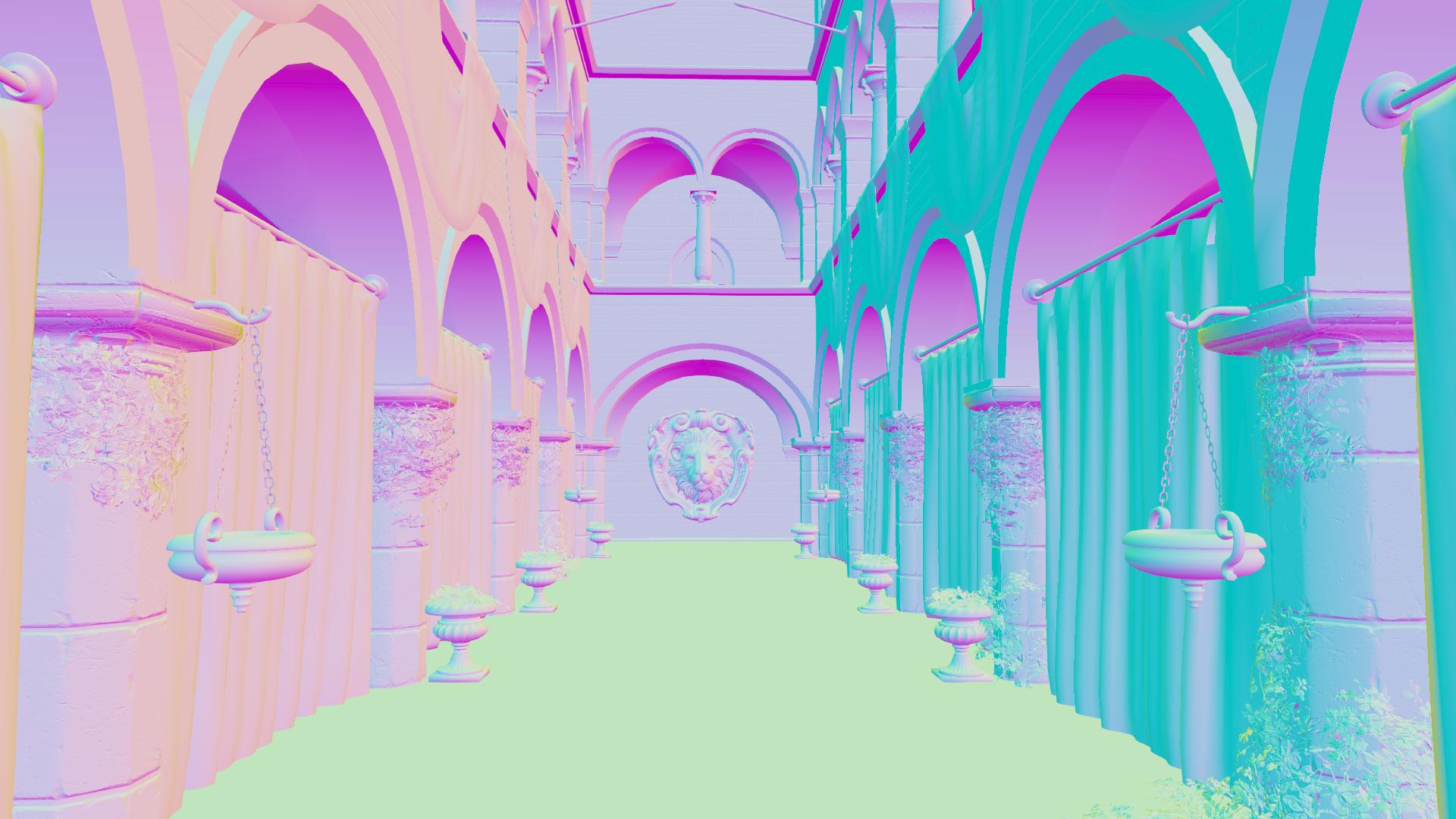
Remember that we have a half-resolution texture with the SSAO color output and we need to calculate the color of each fragment that will be written in the full-resolution image. In order to find this color, in the upsampling pixel shader, we need to operate in the samples of each 2×2 neighborhood of the low resolution texture.
Distinguishing the surfaces from the discontinuities
We’ve discussed this part in post 3.1 and post 3.2:
In order to decide if the samples of each 2×2 neighborhood of the low resolution texture belong to the same surface or not, we need information from the normals that correspond to these samples.
As the normals have been calculated for the full resolution image, we need to have bound a downsampled normal buffer for this step where the normals are quite representative of the original ones that would correspond to these samples. We will see how we can perform this downsampling later. For the moment, let’s just assume that we already have a normal buffer of the size of the low resolution SSAO render target, and that each normal of this buffer is the normal that corresponds to the SSAO texture sample that has the same uv coordinates.
The algorithm goes like this:
For each 2×2 neighborhood of the low resolution textures, we calculate the dot products between the normals (3 dot products) and we find the minimum among them. If this minimum has a value close to 1.0 we assume that all the 4 samples lie in the same surface otherwise we assume that there is a surface discontinuity in the neighborhood.
This is because (as we’ve seen in post 3.2) the dot product between 2 normals a and b can be expressed as:
|
1 |
a · b = |a| * |b| * cosθ |
where θ is the angle between the normals.
As the downsampled normals are already normalized in this shader:
|
1 |
|a| * |b| = 1 => a · b = cosθ |
This equation makes clear that when the samples lie in the same surface (and their normals are almost parallel) the angle θ between every two of them is small (close to zero), and so the dot product takes a value close to 1.0 (because cos0 = 1).
So, it’s enough to check if the minimum dot product among the dot products of the normals of the neighborhood is close to 1.0: as the dot product (cosθ) can take values from 0.0 to 1.0, when the minimum dot product of the neighborhood takes a value close to 1.0 all the other dot products also take values close to 1.0, and so all the four normals are almost parallel to each other and all four samples lie in the same surface.
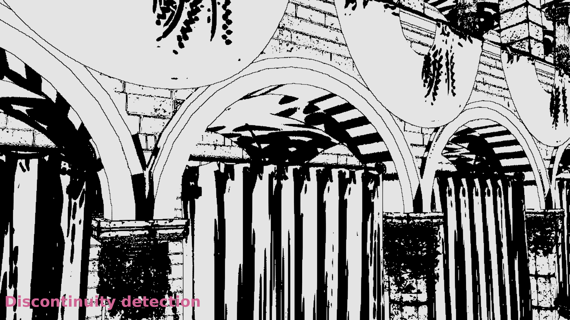
The comparison of this minimum dot product with a threshold close to 1 can be used to generate a “mask” for each frame where the surface neighborhoods are painted in white and the discontinuity neighborhoods are painted in black in order to visualize this classification:
The idea to classify the sample neighborhoods and perform different sampling depending on if they are surfaces or not comes from an article on Call of Duty Black Ops 3 [3]. As we’ve seen in post 3.1 the author performed a similar classification using the depths of each neighborhood. For reasons already explained in that previous post, I preferred to modify his method and use the dot products between the normals instead.
Linear interpolation on surfaces
We already said that when the samples lie on a surface, the color is the result of the linear interpolation that is performed by the hardware (weighted average with the weights being the Manhattan distances from each sample, see also the OpenGL Reference sections on Texture Minification/Magnification):
|
1 |
texture(ssao_tex_linear_sampler, uv); |
where the sampler performs linear filtering (VK_FILTER_LINEAR) and uv are the texture coordinates.
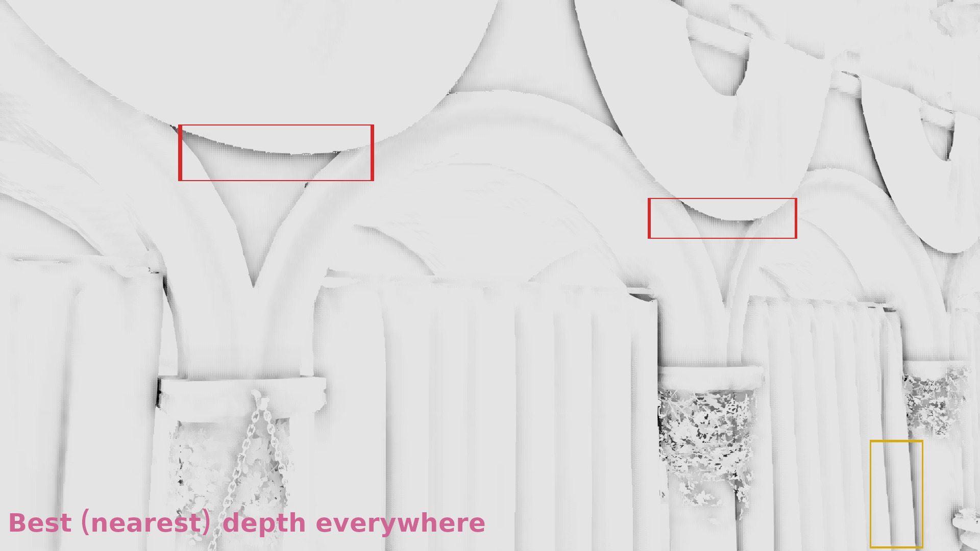
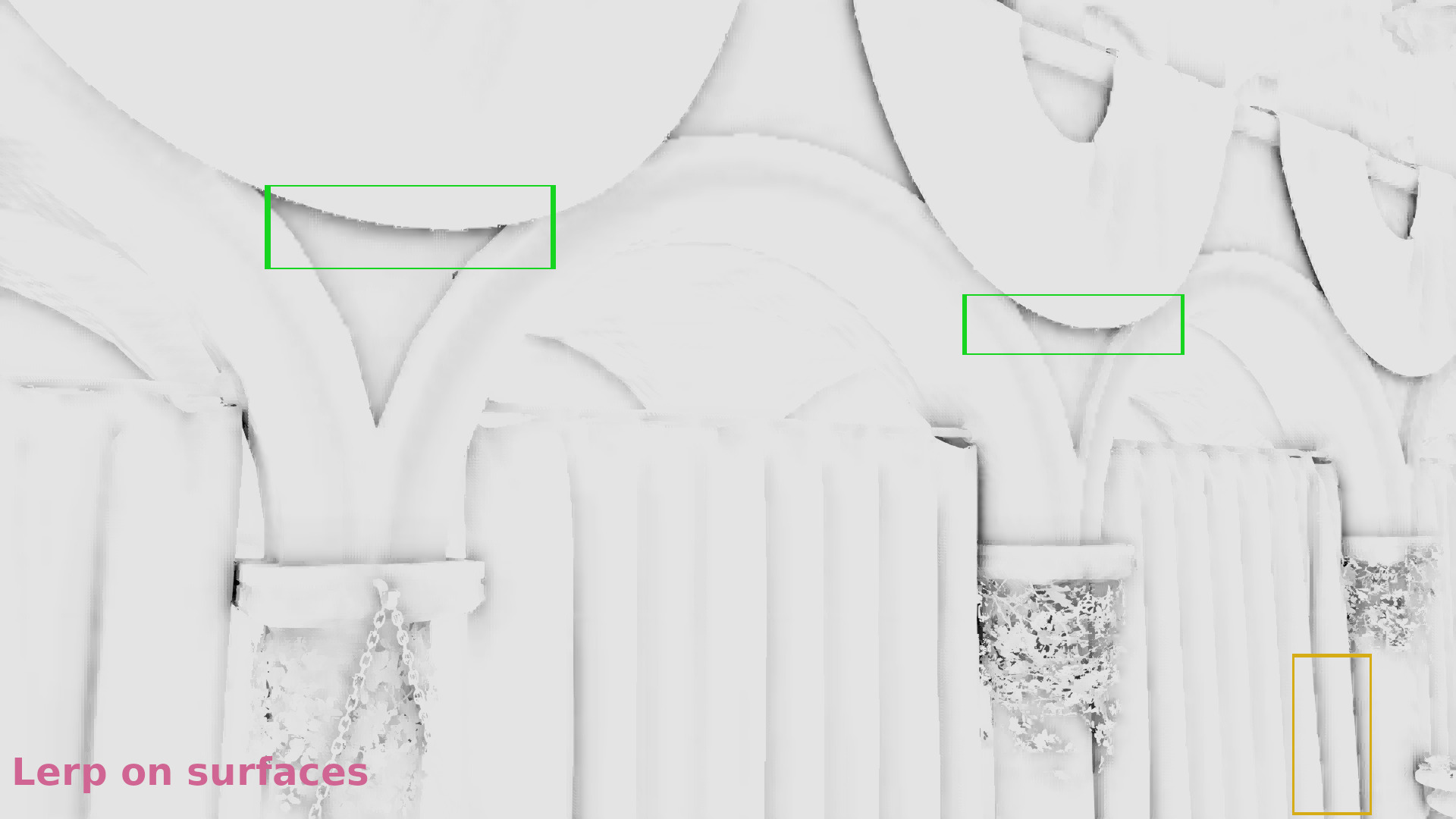
The effect of using lerp on surfaces can be seen in the following images from part 4 (see the shadows in the red and green quads):
Nearest depth upsampling
We’ve discussed this part in post 1:
When a 2×2 neighborhood contains a discontinuity, we perform the Nearest Depth algorithm.
In order to perform the nearest depth algorithm for each SSAO texture sample, we need information about its depth. So, here we have the same problem we had with the normals: our z-buffer values correspond to the high resolution image. Which again means the same thing: at this step we need to have a downsampled version of the z-buffer as well that has the size of the low resolution SSAO render target and where the depths are quite representative of the depths that would correspond to the SSAO samples in the same uv coordinates if the SSAO was performed in a full resolution render target.
We’ll talk about the downsampling later, at this point we’ll only assume that we already have bound such a downsampled depth buffer in the upsampling pixel shader, and that we also have bound the original z-buffer.
And so: in every 2×2 neighborhood of the downsampled z-buffer, we find the sample whose depth is closer to the original depth from the original high resolution depth buffer and we select the SSAO texture sample that has the same uv coordinates with this sample to calculate the AO color for the fragment.
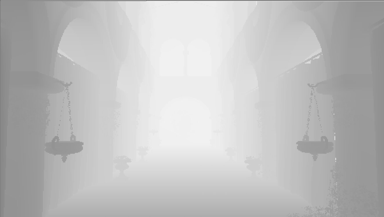
At the end of the upsampling part (where we upsampled the SSAO texture by performing lerp on surfaces and nearest depth on discontinuities) we’ve calculated the AO of each frame. The result is something like that:
Tweaks
We can further tweak the discontinuity detection as we’ve seen in post 5 to select a samples classification threshold that reduces any lerp artifacts while it preserves the smoothing:
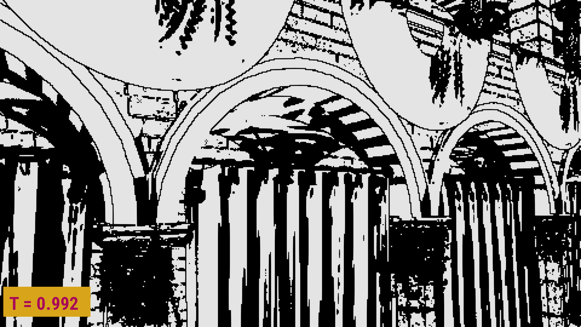

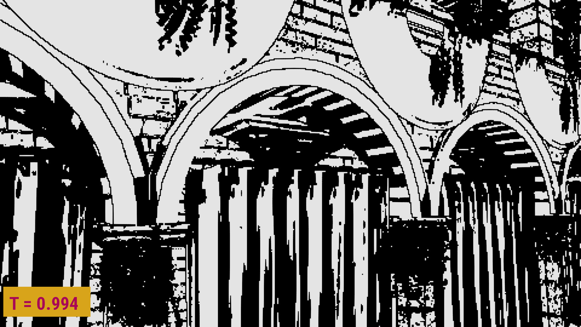

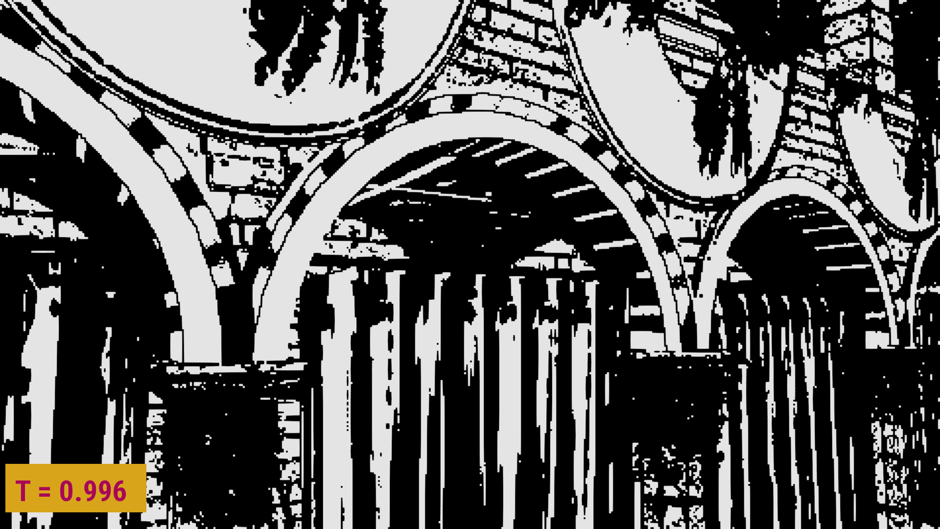
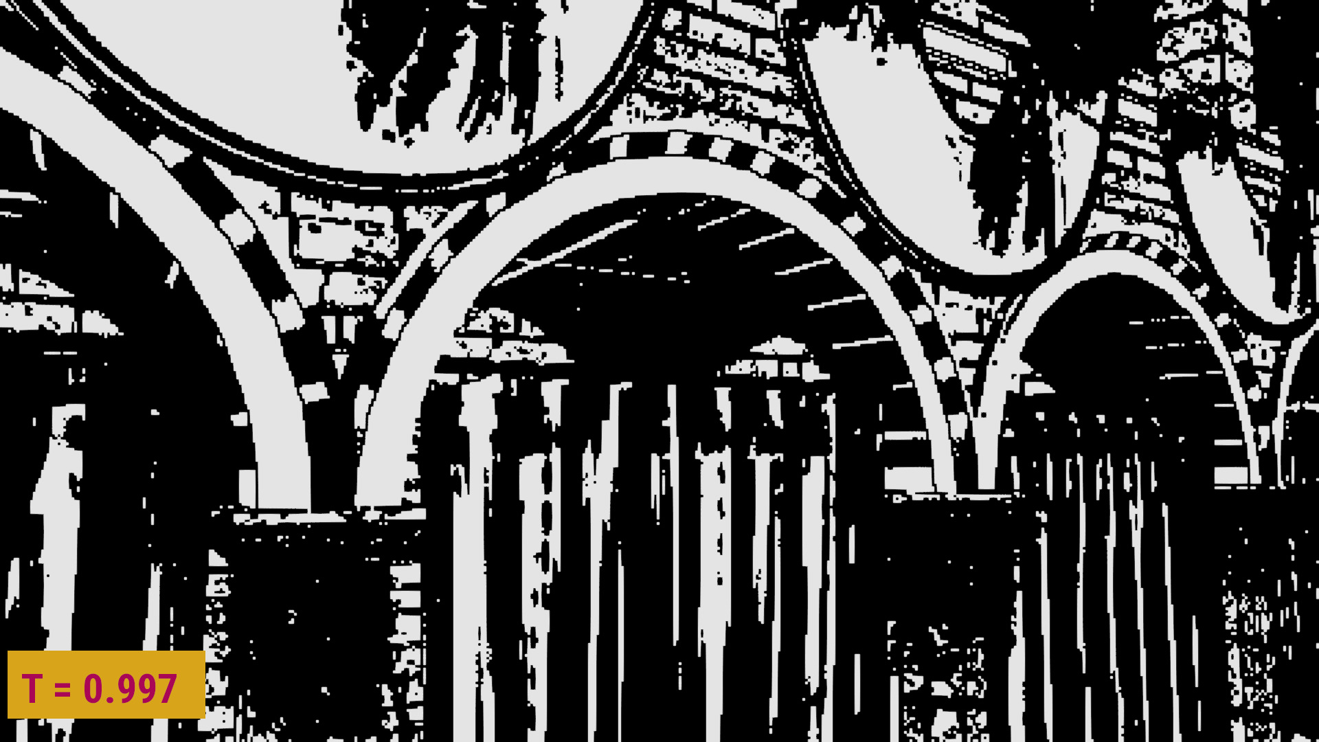


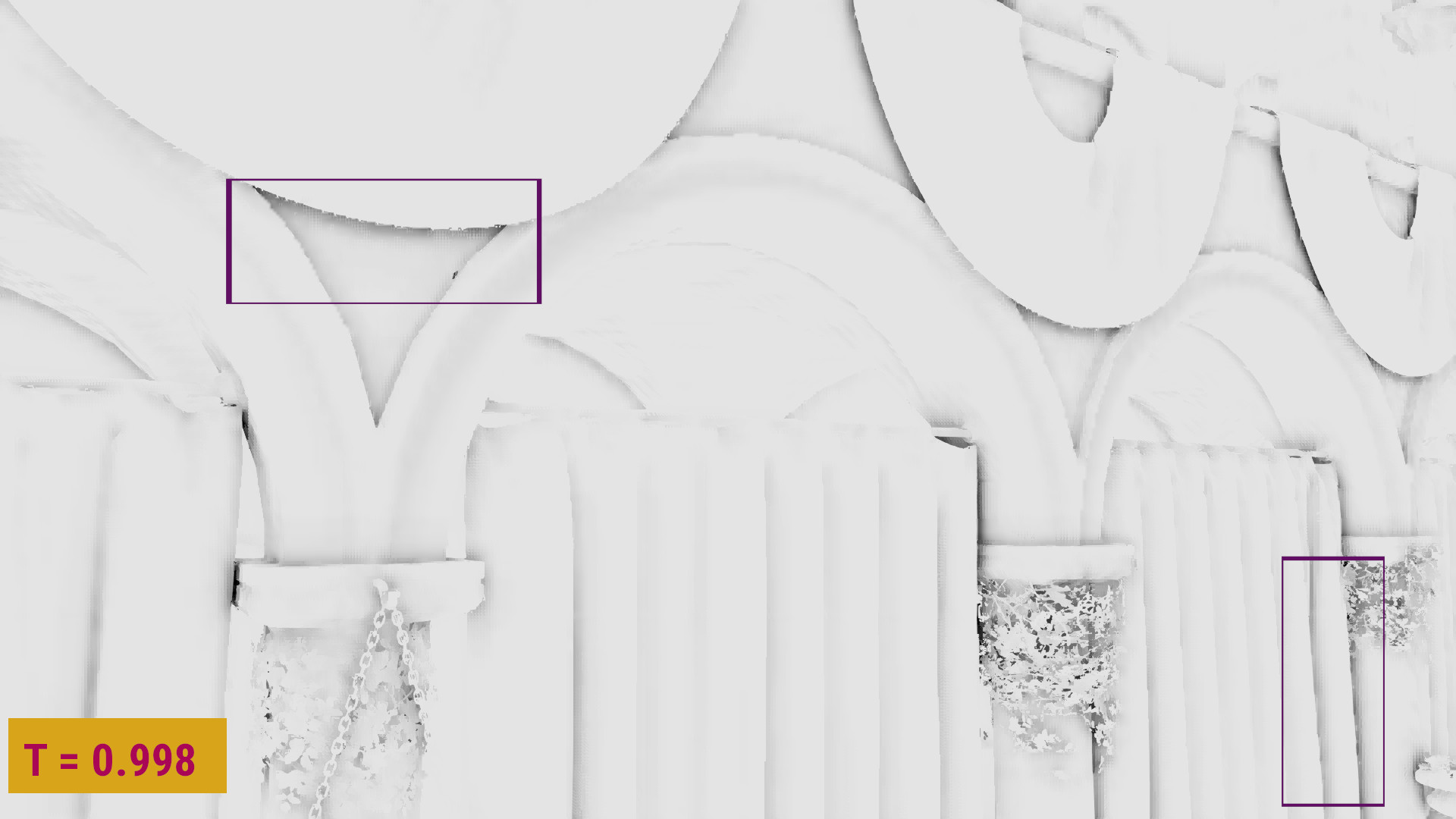
For the sponza scene I had selected a threshold of 0.997 (although in my first comparisons I was using 0.992).
Downsampling the depth and normal buffers
We’ve discussed the downsampling in post 2 and post 4:
I needed the downsampled z-buffer to be quite representative of the original surface, in order to improve the nearest depth selection during the upsampling step. For the normals, it was enough to select the samples that had the same uv coordinates with the selected depths (see also part 3.2).
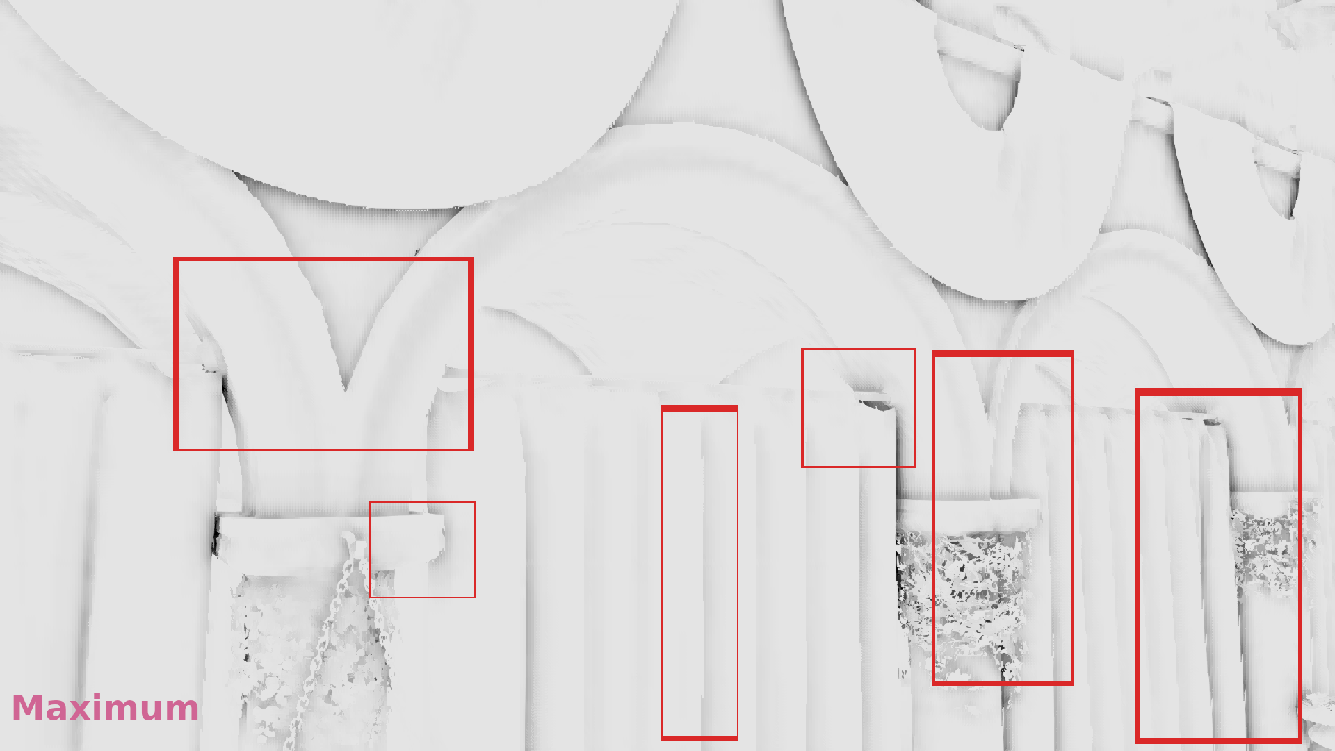
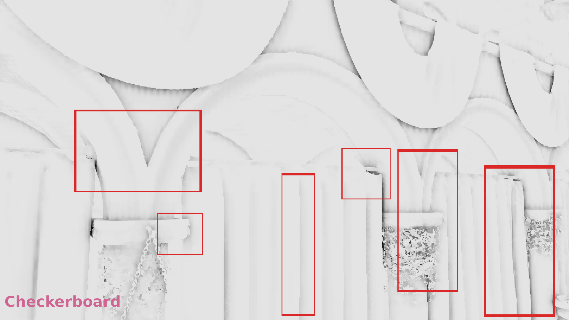
After having compared different z-buffer downsampling techniques that were selecting the minimum, the maximum or a combination of the two following some pattern (part 4), I tried a completely different approach that seemed to work very well with the nearest depth:
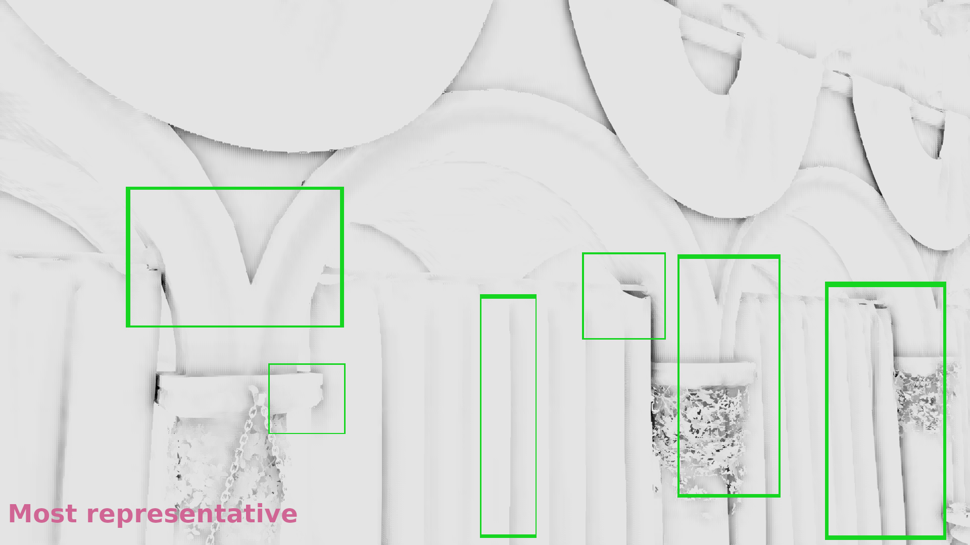
My idea was to select the most representative depth of each 2×2 neighborhood of the original depth buffer by doing the following:
In each 2×2 neighborhood I’ve calculated the centroid (which equals the average depth in this case). Then I’ve calculated each depth’s distance from this centroid and I rejected the sample that had the maximum one. For the remaining 3 samples, I’ve calculated a new centroid and I rejected again the sample with the maximum distance. Then, I repeated for the last two samples until I only had one: the most representative sample of the surface.
The nearest depth results were improved with this method. Here’s a gallery from part 4 where the AO results from algorithms discussed in parts 1, 2 and 4 are compared to the AO results with this new downsampling method in 1/4 resolution (for the artifacts to be more visible):
Implementation details
Depth and normal buffers downsampling:
Let’s first see how the z-buffer and normal buffer downsampling can be performed:
Vulkan side, we need a separate pass that downsamples the two buffers. The vertex shader of the pass just draws a quad, whereas the pixel shader takes as input the samplers of the original depth and normal buffers and performs the downsampling by writing the output colors in one or more half resolution render targets. For performance reasons, I only used one output: a 32-bit (to fit the depth value size) RGBA color attachment, where the rgb color values contained the xyz coordinates of the normal directions and the a values contained the depths. More details in some parameters of the pass can be found in post 3.2. The most important part was that the samplers must use VK_FILTER_NEAREST, as we DON’T want to use any filtering (as we are going to perform the sampling ourselves).

Vertex shader (only renders a quad):
|
1 2 3 4 5 6 7 8 9 10 11 12 13 14 15 16 |
#version 430 #extension GL_ARB_separate_shader_objects : enable layout(location = 0) out vec2 out_uv; const vec2 vdata[] = vec2[] ( vec2(1.0, 1.0), vec2(1.0, 0.0), vec2(0.0, 1.0), vec2(0.0, 0.0)); void main() { out_uv = vdata[gl_VertexIndex]; gl_Position = vec4(vdata[gl_VertexIndex] * 2.0 - 1.0, 0.0, 1.0); } |
Pixel shader (performs the downsampling):
Selecting the most representative samples:
|
1 2 3 4 5 6 7 8 9 10 11 12 13 14 15 16 17 18 19 20 21 22 23 24 25 26 27 28 29 30 31 32 33 34 35 36 37 38 39 40 41 42 43 44 45 46 47 48 49 50 51 52 53 54 55 56 |
float most_representative(sampler2D tex_depth, vec2 in_uv) { float samples[] = float[] ( textureOffset(tex_depth, in_uv, ivec2(0, 0)).x, textureOffset(tex_depth, in_uv, ivec2(0, 1)).x, textureOffset(tex_depth, in_uv, ivec2(1, 0)).x, textureOffset(tex_depth, in_uv, ivec2(1, 1)).x); float centr = (samples[0] + samples[1] + samples[2] + samples[3]) / 4.0; float dist[] = float[] ( abs(centr - samples[0]), abs(centr - samples[1]), abs(centr - samples[2]), abs(centr - samples[3])); float max_dist = max(max(dist[0], dist[1]), max(dist[2], dist[3])); float rem_samples[3]; int rejected_idx[3]; int j = 0; int i; int k = 0; for (i = 0; i < 4; i++) { if (dist[i] < max_dist) { rem_samples[j] = samples[i]; j++; } else { /* for the edge case where 2 or more samples have max_dist distance from the centroid */ rejected_idx[k] = i; k++; } } /* also for the edge case where 2 or more samples have max_dist distance from the centroid */ if (j < 2) { for (i = 3; i > j; i--) { rem_samples[i] = samples[rejected_idx[k]]; k--; } } centr = (rem_samples[0] + rem_samples[1] + rem_samples[2]) / 3.0; dist[0] = abs(rem_samples[0] - centr); dist[1] = abs(rem_samples[1] - centr); dist[2] = abs(rem_samples[2] - centr); float min_dist = min(dist[0], min(dist[1], dist[2])); for (int i = 0; i < 3; i++) { if (dist[i] == min_dist) return rem_samples[i]; } /* should never reach */ return samples[0]; } |
Note that the code is slightly different from what I described earlier: here I select the sample that is closer to the centroid when we have 3 samples as the remaining 2 samples have the same distance from their centroid, so I could safely pick any of them without really affecting the results. (Thanks zrizi for pointing this out in the comments.)
Performing the depth and normal buffers downsampling:
|
1 2 3 4 5 6 7 8 9 10 11 12 13 14 15 16 17 18 19 20 21 22 23 24 25 26 27 28 |
layout(set = 0, binding = 0) uniform sampler2D tex_depth; layout(set = 0, binding = 1) uniform sampler2D tex_normal; layout(location = 0) in vec2 in_uv; layout(location = 0) out vec4 out_color; void main() { float d[] = float[] ( textureOffset(tex_depth, in_uv, ivec2(0, 0)).x, textureOffset(tex_depth, in_uv, ivec2(0, 1)).x, textureOffset(tex_depth, in_uv, ivec2(1, 0)).x, textureOffset(tex_depth, in_uv, ivec2(1, 1)).x); vec3 n[] = vec3[] ( textureOffset(tex_normal, in_uv, ivec2(0, 0)).xyz, textureOffset(tex_normal, in_uv, ivec2(0, 1)).xyz, textureOffset(tex_normal, in_uv, ivec2(1, 0)).xyz, textureOffset(tex_normal, in_uv, ivec2(1, 1)).xyz); float best_depth = most_representative(tex_depth, in_uv); for (int i = 0; i < 4; i++) { if (best_depth == d[i]) { out_color = vec4(n[i], d[i]); return; } } } |
Upsampling pixel shader:
Nearest depth:
|
1 2 3 4 5 6 7 8 9 10 11 12 13 14 15 16 17 18 19 20 21 22 23 24 25 26 27 28 29 30 31 32 |
float nearest_depth_ao(in sampler2D tex_ssao_nearest, in sampler2D tex_ssao_dnbuf, in sampler2D tex_depth, in vec2 in_uv) { float d[] = float [] ( textureOffset(tex_ssao_dnbuf, in_uv, ivec2(0, 0)).a, textureOffset(tex_ssao_dnbuf, in_uv, ivec2(0, 1)).a, textureOffset(tex_ssao_dnbuf, in_uv, ivec2(1, 0)).a, textureOffset(tex_ssao_dnbuf, in_uv, ivec2(1, 1)).a); float ao[] = float[] ( textureOffset(tex_ssao_nearest, in_uv, ivec2(0, 0)).r, textureOffset(tex_ssao_nearest, in_uv, ivec2(0, 1)).r, textureOffset(tex_ssao_nearest, in_uv, ivec2(1, 0)).r, textureOffset(tex_ssao_nearest, in_uv, ivec2(1, 1)).r); float d0 = texture(tex_depth, in_uv).r; float min_dist = 1.0; int best_depth_idx; for (int i = 0; i < 4; i++) { float dist = abs(d0 - d[i]); if (min_dist > dist) { min_dist = dist; best_depth_idx = i; } } return ao[best_depth_idx]; } |
Linear interpolation:
|
1 2 3 4 5 |
float lerp_ao(in sampler2D tex_ssao_linear, in vec2 in_uv) { return texture(tex_ssao_linear, in_uv).r; } |
Selecting the right upsampling method using information from the normals of the neighborhood:
|
1 2 3 4 5 6 7 8 9 10 11 12 13 14 15 16 17 18 19 20 21 22 23 |
float calc_ao(in sampler2D tex_ssao, in sampler2D tex_ssao_nearest, in sampler2D tex_ssao_dnbuf, in sampler2D tex_depth, in vec2 in_uv) { vec3 n[] = vec3[] ( textureOffset(tex_ssao_dnbuf, in_uv, ivec2(0, 0)).rgb, textureOffset(tex_ssao_dnbuf, in_uv, ivec2(0, 1)).rgb, textureOffset(tex_ssao_dnbuf, in_uv, ivec2(1, 0)).rgb, textureOffset(tex_ssao_dnbuf, in_uv, ivec2(1, 1)).rgb); float dot01 = dot(n[0], n[1]); float dot02 = dot(n[0], n[2]); float dot03 = dot(n[0], n[3]); float min_dot = min(dot01, min(dot02, dot03)); float s = step(0.997, min_dot); return mix(nearest_depth_ao(tex_ssao_nearest, tex_ssao_dnbuf, tex_depth, in_uv), lerp_ao(tex_ssao, in_uv), s); } |
Demos
Nearest depth:
Nearest depth + Lerp (T=0.992):
Nearest depth + Lerp (T=0.997):
Closing
There will always be some visible artifacts with every upsampling method, as it’s impossible to achieve a perfect representation of the original image using the half number of pixels. This method I’ve just presented seems to improve significantly the SSAO quality compared to the ones I’ve tried before (see post 4 for more comparisons) and to reduce the artifacts quite a lot, but I suppose that there are many other ideas to explore out there.
And some good news: you’ve finally reached the end of this post and the series!! See you next time! 🙂
References
[1] Iago’s post on his sponza demo: https://blogs.igalia.com/itoral/2018/04/17/frame-analysis-of-a-rendering-of-the-sponza-model/
[2] NVIDIA’s article on nearest depth: http://developer.download.nvidia.com/assets/gamedev/files/sdk/11/OpacityMappingSDKWhitePaper.pdf
[3] Article on Call of Duty Black Ops 3 upsampling: http://c0de517e.blogspot.com/2016/02/downsampled-effects-with-depth-aware.html
Previous posts of the series:
Part 1: Depth-aware upsampling experiments (Part 1: Nearest depth)
Part 2: Depth-aware upsampling experiments (Part 2: Improving the Z-buffer downsampling)
Part 3.1: Depth-aware upsampling experiments (Part 3.1: Improving the upsampling using depths to classify the samples)
Part 3.2: Depth-aware upsampling experiments (Part 3.2: Improving the upsampling using normals to classify the samples)
Part 4: Depth-aware upsampling experiments (Part 4: Improving the nearest depth where we detect discontinuities)
Part 5: Depth-aware upsampling experiments (Part 5: Sample classification tweaks to improve the SSAO upsampling on surfaces)
The last comparison you make between 2 remaining samples in most_representative when downsampling is redundant; you always compare the same value and always pick d2[1].
Instead, when you’re down to 3 samples after the first round, maybe you should just pick up the sample which is the nearest to the centroid between the 3? This will ensure you’re still getting rid of the farthest sample, but now you’re picking a better representation (because currently comparing 2 samples at the end always return the same value d2[1]).
Yes, the centroid of the remaining two samples is a sample that has the same distance from both and as a result the first is always selected. I should definitely get rid of this last check! I will fix the shader and update the post.
Thank you! 🙂