This is another post of the series where I explain the ideas I try in order to improve the upsampling of the half-resolution SSAO render target of the VKDF sponza demo that was written by Iago Toral. In a previous post (3.2), I had classified the sample neighborhoods in surface neighborhoods and neighborhoods that contain depth discontinuities using the normals. Having this information about the neighborhoods, in the last post, I demonstrated how to further improve the nearest depth algorithm (that was explained in parts 1 and 2 of these series) and reduce the artifacts in the neighborhoods where we detect depth discontinuities. The result was good but we’ve seen that there are still some imperfections in a few edge cases. So, in this post, I am going to talk about some ideas I had to further improve the SSAO and my final decisions.
Before I start a quick overview of my previous posts:
- In parts 1 and 2, I explained the concept of the depth aware upsampling, and the nearest depth algorithm from NVIDIA. I’ve also described some methods I’ve found in articles about it ([1], [2]) to perform the z-buffer downsampling that is an important step of this algorithm. We’ve seen that selecting the maximum depth in each 2×2 neighborhood or selecting once the min once the max following a checkerboard pattern doesn’t make much difference in the final nearest depth and that the nearest depth can improve the upsampling in corners, edges and regions where we have a depth discontinuity.
- In part 3.1, I tried to classify the samples 2×2 neighborhoods to surface neighborhoods and to neighborhoods that contain discontinuities using the depth as it was suggested in an article about the upsampling used in Call of Duty Black Ops 3. The idea was to perform linear interpolation on surfaces and nearest depth where discontinuities are detected. I’ve shown that this method cannot work very well in our case, as it depends on what is visible on the screen when we perform the “discontinuity detection” and on the positions of the near and far clipping planes.
- In part 3.2, I tried to perform the same classification using the normals and I achieved a much better result. Then I performed the nearest depth on discontinuities and linear interpolation on surfaces and the result was acceptable although there were some visible artifacts.
- In part 4, I implemented an idea I had for the z-buffer downsampling in order to improve the nearest depth where discontinuities were detected by the previous (3.2) classification using the normal. The idea was to select the most representative depth of each neighborhood by calculating the sample distances from the neighborhood centroid, rejecting the sample that has the maximum distance and repeating for the sub-neighborhoods until 1 sample remains. It was an improvement compared to selecting the maximum or once the minimum once the maximum following some pattern and it didn’t have significant difference in performance.
So, in the last post, we’ve seen that combining lerp with nearest depth, is causing some small artifacts in some edge cases like in some surface neighborhoods that are very very close to discontinuity neighborhoods. Let’s see again the 1/2 (target) resolution example:


By observing the pixels where the artifact occurs in this particular frame, we can see that we have tiny surface neighborhoods (bright regions) inside discontinuity neighborhoods (dark regions).
Ideally, I wanted to get rid of such edge-case artifacts too. So, my first approach was to check if I could somehow improve the smoothing on such edge-case surfaces. I had some ideas to try here. One of them was to replace the weighted average with some sort of gaussian smoothing in order to have smoother colors close to the center of the white regions and less close to the edges. Another was to interpolate the result of the texture2d-lerp with the darker color of the neighborhood to “cover” the sudden “white” (surface) artifacts. And actually I implemented the latter like: lerp(bilerp(uv), darker_color_of_the_neighborhood, scale_metric(SSAO_DOWNSCALE)); where the scale metric was a function of the SSAO downscale factor and it worked more or less OK. Nevertheless, I found it too hacky and I had serious doubts that this could work well in other scenes and with any discontinuity detection without needing a lot of tweaking.
After observing different frames, I realized that the idea to “improve” the smoothing by implementing and tweaking some other method or hack than lerp was not a good one as the advantage of using the built-in texture2D is not only the smooth AO colors on surfaces but also the speed of the fragment color calculation in regions where the colors are continuous and we don’t care so much about the selection (surfaces), as the built-in texture2d is optimized by the hardware.
So, at this point, I decided that instead of introducing a new hack and have to tweak it, it’s better to tweak my samples classification and decide if I prefer to have more artifacts from the nearest depth (less smoothing more pixelized appearance, see part 4 for the effect of lerp) or more artifacts from the lerp (artifacts in tiny surface neighborhoods that could be classified as discontinuities after tweaking the samples classification).
For this scene, I’d like to keep the smoothing from lerp, but I would prefer to perform nearest depth in the tiny regions like those we spot in curtains in the galleries above. So, I increased the discontinuity detection threshold (discussed in part 3.2) until most of the tiny white regions of pixels in the “edge-detection-like” image disappear (were classified as discontinuities) while paying attention to not increase it so much that too many nearest-depth artifacts appear in other places.
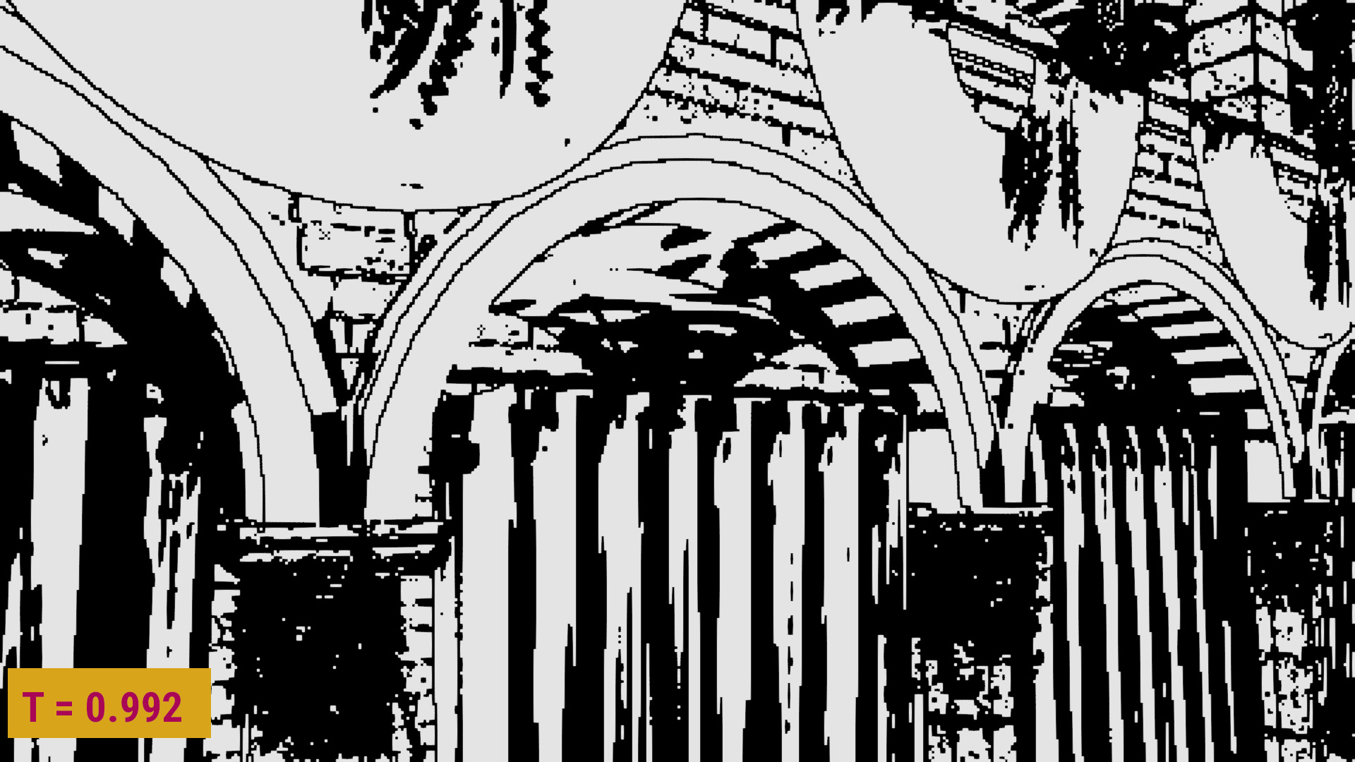
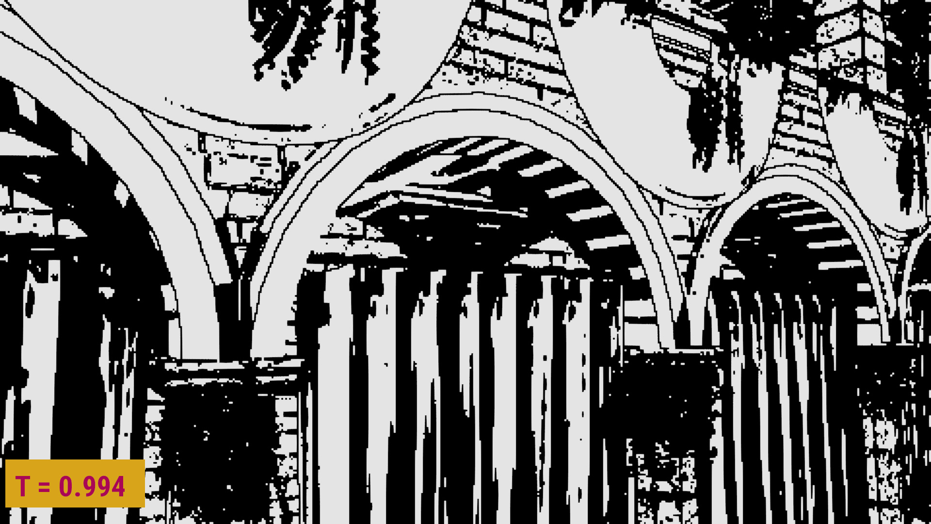
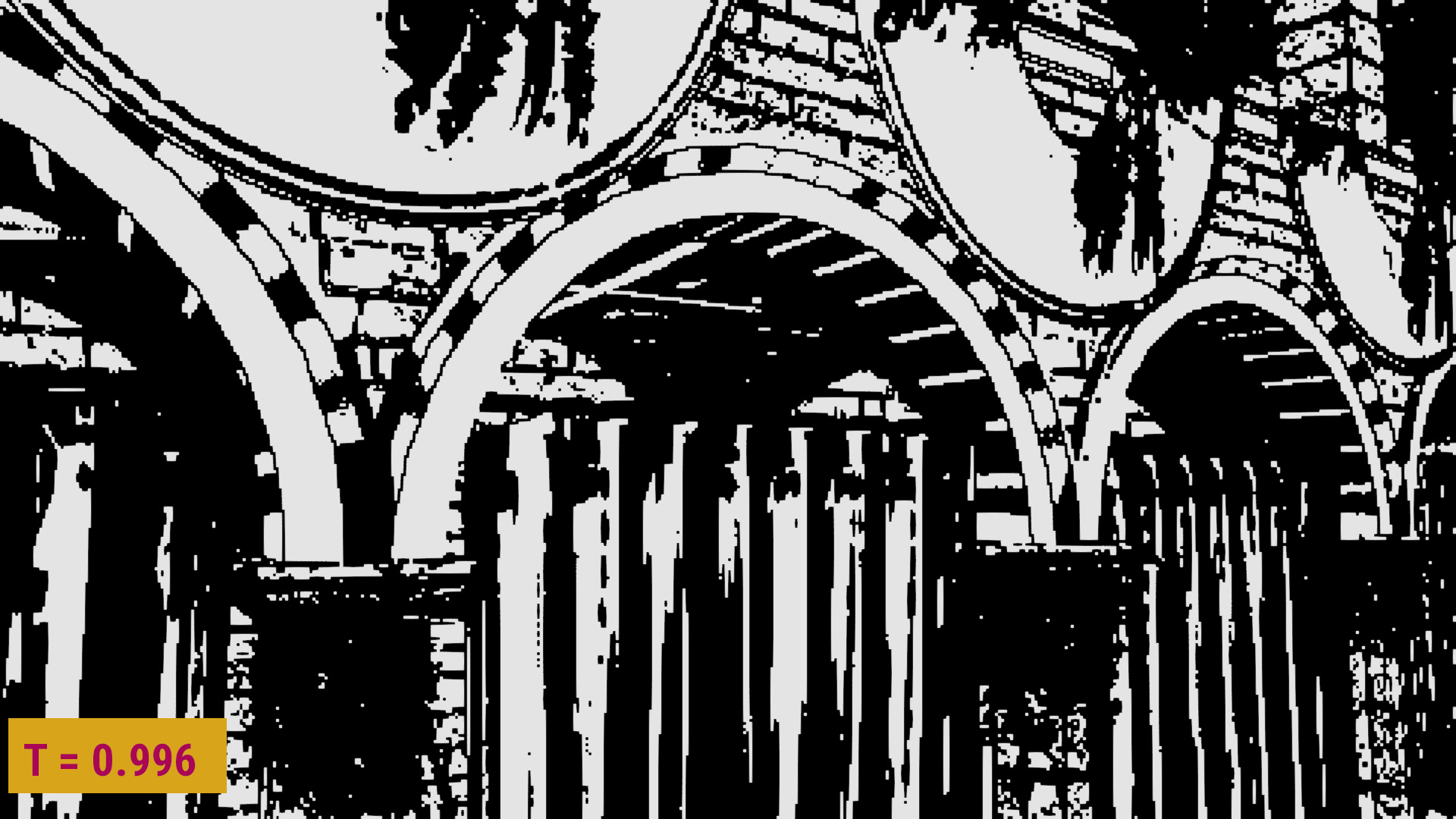
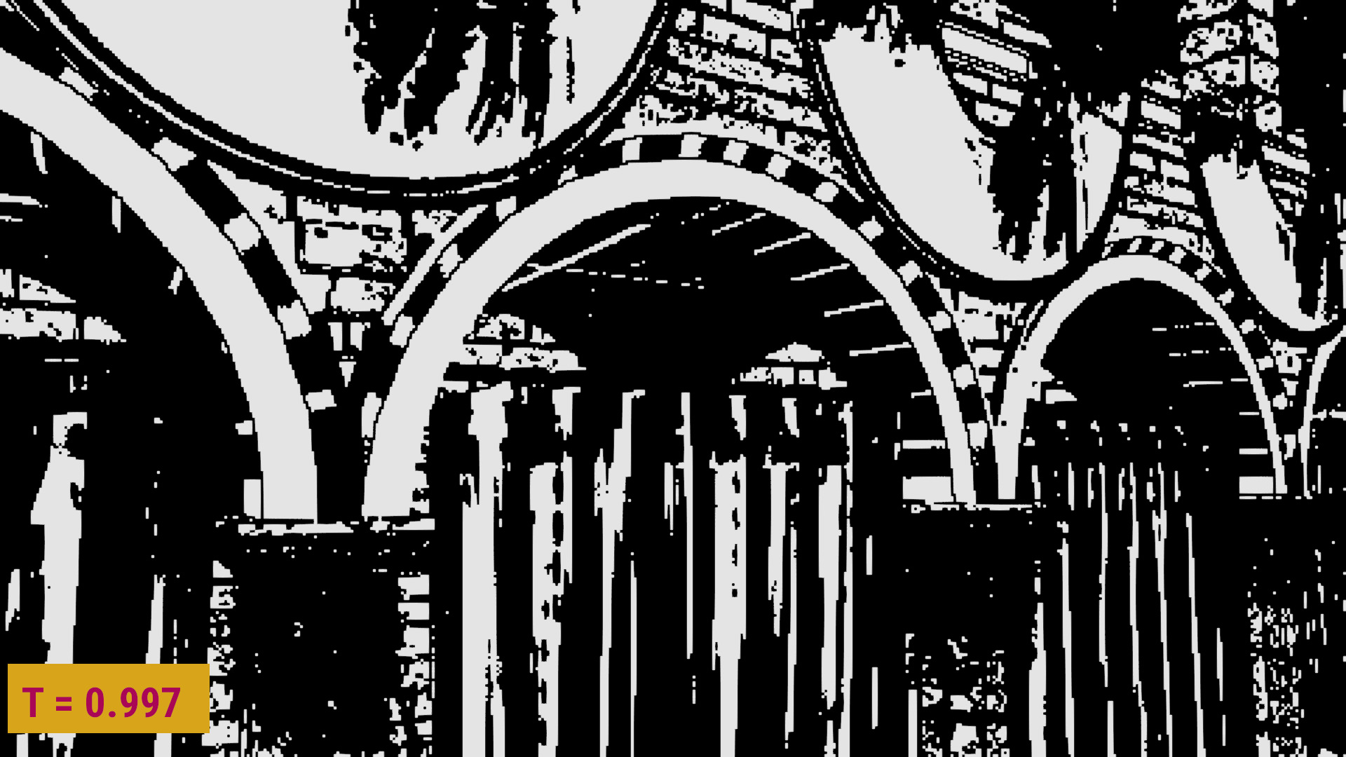
Let’s see how the discontinuity detection and AO vary in 1/4 resolution (for the artifacts to be more visible) while we increase the threshold (more nearest depth):
Samples classification:


The AO from T=0.995 to T=0.998:


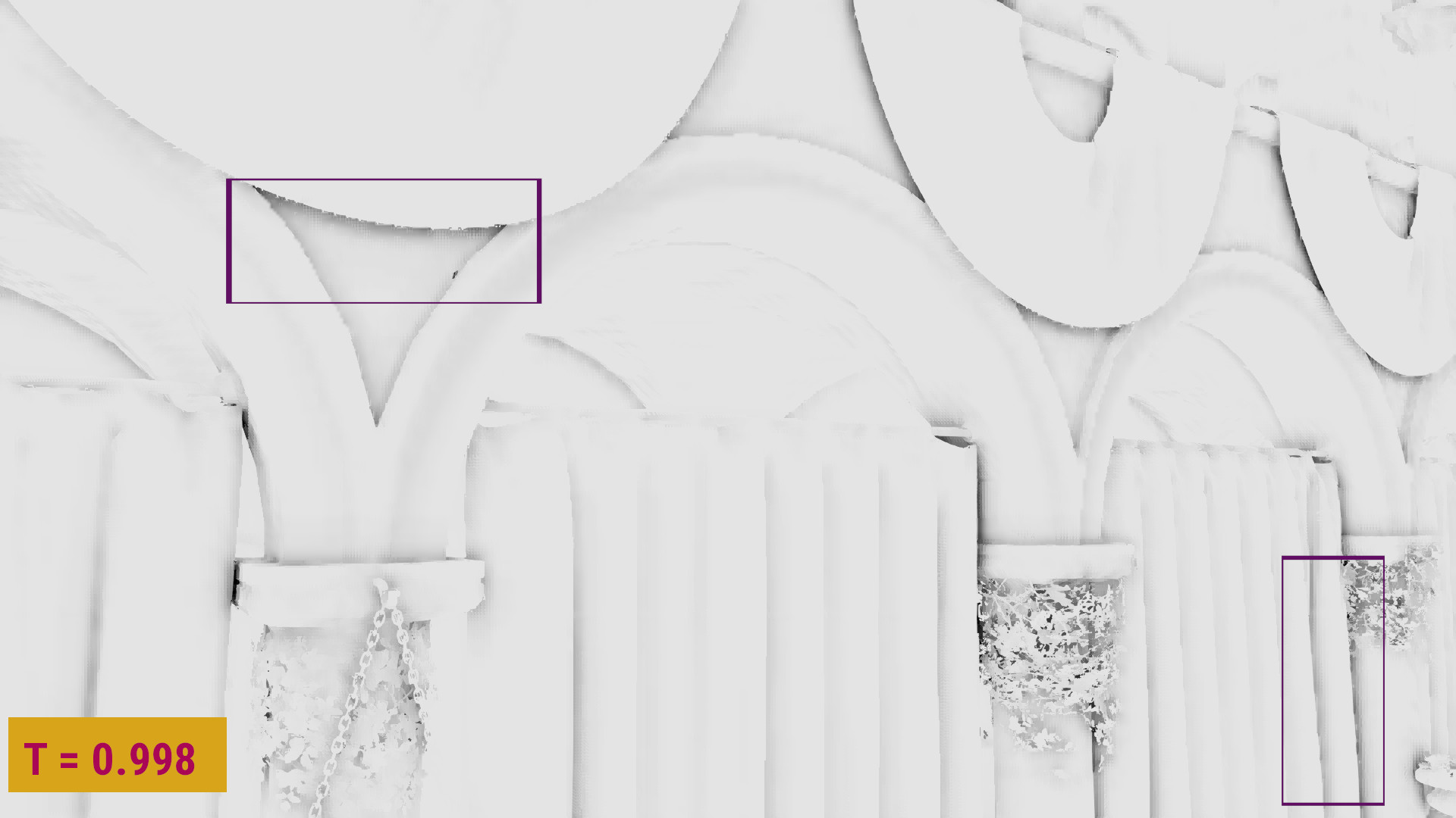
In 1/2 resolution the imperfections were even less visible. After having compared several different frames using different thresholds, I’ve just chosen a threshold that seemed to reduce the lerp artifacts in most of them while it preserved most of the smoothing. That was T=0.997. The SSAO was improved but obviously this tweaking should be done for every different scene, every time we use this algorithm.
And even after tweaking, it was impossible to reduce all the artifacts for all the views of the scene, as you can see on the video below:
This was expected as it’s impossible to have a perfect representation of the full resolution image using the half pixels only. So, at this point I’ve stopped performing further experiments, although I was still feeling that there could be many other methods to try out there… 🙂
Other videos when T=0.997:
Samples classification:
AO:
Conclusions/Summary
There might be many ways to achieve a smooth appearance on surface neighborhoods, but as all of them will need tweaking and cause some artifacts anyway, it’s probably better to just keep the linear interpolation that is performed by the hardware optimized GLSL texture function. Then, one can decide which artifacts can be tolerated and which should be removed and tweak the discontinuity detection accordingly by modifying the threshold.
The reasons:
- The built-in GLSL
texture2dfunction is a very fast solution for the neighborhoods where the depth values aren’t so important (surfaces). - The difference in the amount/distribution of smoothing is not so visible in 1/2 resolution, so just tweaking the discontinuity detection is enough to reduce most of the artifacts caused by lerp.
- We can’t fix all the edge cases of any method, as a perfect reconstruction using the half pixels only is impossible anyway, and so, any further experiments are mostly useful as an academic research than a way to achieve even more visible improvements.
Next post
At this point, we have a method that gives an acceptable AO after the upsampling in most points and each part and idea of it is explained in a different post. So in the next and final post of these series I am only going to present it completed.
Links
Articles:
[1]: On nearest depth: http://developer.download.nvidia.com/assets/gamedev/files/sdk/11/OpacityMappingSDKWhitePaper.pdf
[2]: On upsampling techniques used in Call of Duty Black Ops 3:
http://c0de517e.blogspot.com/2016/02/downsampled-effects-with-depth-aware.html
Iago‘s post on his VKDF sponza demo:
https://blogs.igalia.com/itoral/2018/04/17/frame-analysis-of-a-rendering-of-the-sponza-model/
Previous posts of mine:
– part 1: https://eleni.mutantstargoat.com/hikiko/on-depth-aware-upsampling
– part 2: https://eleni.mutantstargoat.com/hikiko/depth-aware-upsampling-2
– part 3.1: https://eleni.mutantstargoat.com/hikiko/depth-aware-upsampling-3-1
– part 3.2: https://eleni.mutantstargoat.com/hikiko/depth-aware-upsampling-3-2
– part 4: https://eleni.mutantstargoat.com/hikiko/depth-aware-upsampling-experiments-4