This is a path tracer I wrote from scratch in C++ for my Advanced Modelling, Rendering and Animation assignment.

I used SDL to present the pixels to the user and I based the code in a ray tracer I wrote some months ago (here is the post). You can download the code (svn://quasar.dnsalias.com/eleni/path_tracer/), the report, the Linux 32 bit binary, the Linux 64 bit binary, the Win32 executable, the MacOSX binary and the README file with instructions on how to run the program. Below are some shots and explanations:
Requirement 1: Many rays per pixels using stratification and jittering:
The pixel is divided recursively to 4 subpixels according to the desired number of rays per pixel (this number is passed as a parameter and is rounded to a power of four). Then the center of each sub-pixel is randomly moved in an area between the boundaries of the sub-pixel. Below, we can see some images produced for different numbers of pixels:
Requirement 2: Use of spherical, triangular & quadrilateral area light sources:
The path tracer (that was still a Monte Carlo ray tracer in this stage) supports spheres, sphere flakes, planes, meshes of quads and meshes of triangles. From those objects, the spheres, the triangle – meshes and the quad – meshes can be used also as area lights. Instead of sending a ray to a point light source and test if our object of interest is in shadow or not, now we use a random point in the surface of the area light. In case of the sphere area lights, points are generated in the bounding cube until one is found to be inside the sphere (rejection sampling). In case of the triangular meshes, a triangle of the mesh is chosen randomly. Then, a point inside this triangle is chosen by calculating random α, β and γ barycentric coordinates between 0 and 1. If α, β and γ have sum greater than one we reject the point (rejection sampling) otherwise we calculate its Cartesian coordinates. In case of quadrilateral meshes, a quad of the mesh is chosen at random and then a random point in that quad is generated. In order to generate a random point in a quad, a random linear combination of 2 vectors of 2 consecutive edges of the quad is used. In the following 3 pictures a scene is lit firstly by using a sphere area light, then by using a quad area light and then using a triangular mesh (teapot) area light:
 |
 |
 |
Requirement 3: Sampling the Lambertian and the Phong BRDFs:
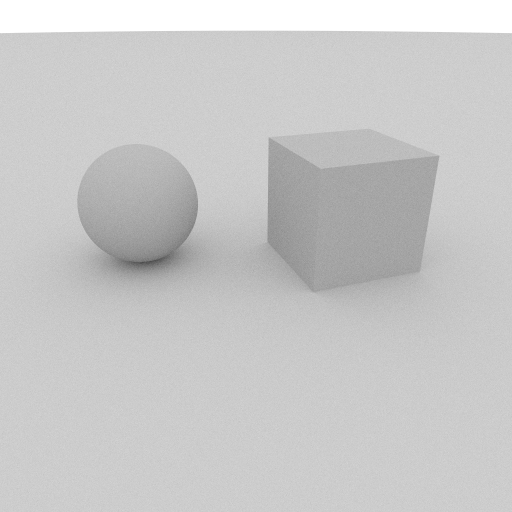
In case of specular surfaces the reflected ray directions form a lobe whereas in case of diffuse surfaces they are scattered in every direction in the hemisphere above the surface. In each case, a random vector was chosen inside the lobe or the hemisphere respectively and the probability to continue tracing or stop was calculated by evaluating the BRDF. In the pictures below, we can see the difference in the reflections of a sphere when sampling the Phong BRDF with various (decremented) specular exponents. We can observe that as the specular exponent is decreased the cone of directions is getting larger:
 |
 |
 |
Requirement 4: BRDF evaluation:
The formulas for the Phong and Lambertian models were used to evaluate the BRDF in case of specular and diffuse surfaces respectively. Case of diffuse interaction: $latex k_d \frac{1}{\pi}$. Case of specular interaction: $latex k_s \frac{m+2}{2\pi}cos^m\alpha$.
Requirement 5: Put it all together to form paths that sample all the integrals:
The path tracer sends many rays per pixel using stratification and jittering. Then, it traces each ray by calling recursively the shade function. In this function it samples each BRDF to decide if the tracing will continue or stop after a specific intersection.
Requirement 6: Russian roulette (unbiased path termination):
The method of Russian roulette was used to implement importance sampling. First, we decide if the next interaction will be diffuse or specular and second, we decide if the tracing will continue or not (unbiased path termination). In the first case, a random number was chosen between 1 and sum of the means of diffuse kd and the specular ks and if it was larger than ks the next interaction was diffuse else it was specular.
In the second case (unbiased path termination), the dot product of the randomly generated vector inside the lobe or the hemisphere (see previous requirement) with the normal of the surface was calculated and compared to the probability evaluated by the BRDF. If it was less or equal to the BRDF value the tracing continued otherwise it stopped.
Requirement 7: Scene creation:
Different scenes were created 🙂 Here are some of them:
Skylight images: a huge hemisphere was used as area light sources to give the impression of skylight. The following scenes were rendered:

 - 1024 rays per pixel.")
Cornell Box: The Cornell Box was rendered with different numbers of rays per pixel:
 |
 |
 |
 |
 |
 |
Other work:
I added also some features to improve the result… e.g. I used gamma-correction to improve the appearance of the colors and a shell script that transforms .OBJ scenes to my scene format to avoid extra pain… 😛 (the teapot for example was generated using a low-polygon version of the Utah teapot…)
looks just great!!! /
The gamma corrected image looks fantastic!
The large hemisphere trick for skylight-like results was neat too.
hahaha!! 🙂
its very very cool
Those skylight pics look very impressive! I liked your ray tracer as well! Keep going!!
Very good, good job hikiko!
OMG! Looks great!! Great job!!
i remember these good times… bring on the GPU ray tracer screen shots! i heard you finished coding! 😉 i need to show you some of mine!
that looks amazing!! the video quality is &£^$*… after tuesday i’ll go over and check it out 😉 i like the kd-tree structure images!
yeah, i hate it when windows has better stuff too, but graphics drivers are mainly developed on that platform… slowly this changes… ATI catalyst 8.7 driver for ATI Radeon HD 5800 is not bad though!
report is going slow…pufff… hopefully i have the background and related work finished tonight so i can start writing the technical chapters..
time
is
running
out…
P.S.: what I said about the windows driver is wrong!! the program seemed to run equally fast!! xD (but windows do have better capturing tools :/ :p)
yassou!
yassou fuzz!